3-94 Keysight B1505A User’s Guide, Edition 12
Accessories
Prepare tools for mounting the socket, screws and nut for socket terminals,
and so on separately.
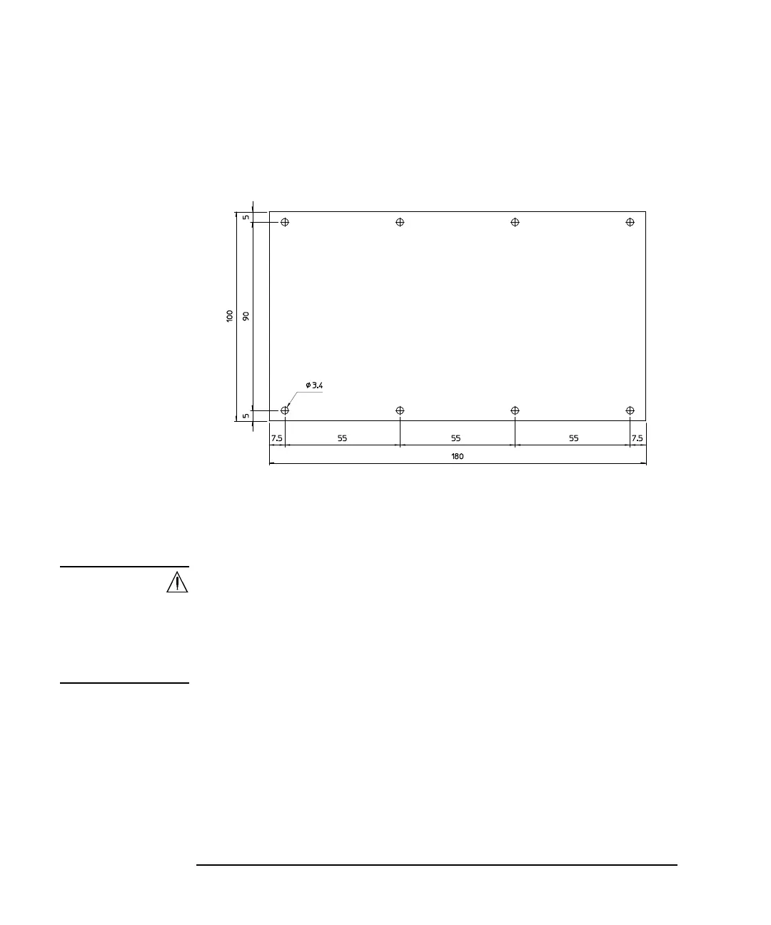
Figure 3-32 Dimensions and Screw Holes of Blank Board
2. Remove the dummy board from the blank module using a T15 Torx
screwdriver.
3. Make a socket board by processing a blank board or the dummy board and
mount your device socket onto the board.
WARNING Make enough space between the socket terminal and the shield/chassis, for
example, about 1 mm for maximum 200 V output and 6 mm for 3000 V, to
prevent discharge and any accident.
Laissez suffisamment d'espace entre la prise borne et la protection/le châssis.
Par exemple, environ 1 mm pour une sortie de 200 V au maximum et 6 mm
pour 3 000 V afin d'éviter toute décharge et tout accident.
4. Fix the socket board to the blank module using the screws and tooth washers
you kept when removing the dummy board.
5. Remove the bottom cover of the blank module using a T10 Torx screwdriver.
6. Assemble cables using the wire and lug terminals.
Cut the appropriate length of the wire, tear off the coating of wire ends, and
then secure the lug terminals to the wire ends using a caulking tool.