Symbol/Field Description
1 m1/m2 points Shows where the measurement markers intersect the selected waveform. Data values atthe bot-
tom of the display are referenced to the intersectlocations of the markers. Calculations arebased
on the data points in between the intersectlocations.
2 Delta Indicates the delta or absolute difference between the markers in units (volts, amps, or watts) and
in time (seconds).
3 m2 Indicates the m2 marker valuein volts, amps, or watts attheintersection point. Also indicates the
distancein time that the m2 marker is in relation to the present trigger position.
4 m1 Indicates the m1 marker valuein volts, amps, or watts attheintersection point. Also indicates the
distancein time of the m1 marker in relation to the present trigger position.
5 Min Indicates the minimum data value (in volts, amps, or watts) between the marker locations of the
selected waveform. Also indicates the distance in time of the minimum value in relation to the
present trigger position.
6 Avg Calculates the average data value (in volts, amps, or watts) between the marker locations of the
selected waveform. Time indicates the timebetween markers over which the averagevalueis
calculated.
7 V p-p Indicates the maximum data value (in volts, amps, or watts) between the marker locations of the
selected waveform. Also indicates the distance in time of the maximum valuein relation to the
present trigger position.
8 Trigger Mode Calculates the differencebetween the maximum and minimum values. Time information is not
valid for calculated p-p values.
Ah (if selected) Calculates the Amp-hours between the marker locations. To view the Amp hours, you may need
to unselectone of the other measurements in the Datalogger Marker Properties window. Only 5
measurements may bedisplayed at a time.
Wh (if selected) Calculates the Watt-hours between the marker locations. To view the Watt hours, you may need to
unselect one of the other measurements in the Datalogger Marker Properties window. Only 5
measurements may bedisplayed at a time.
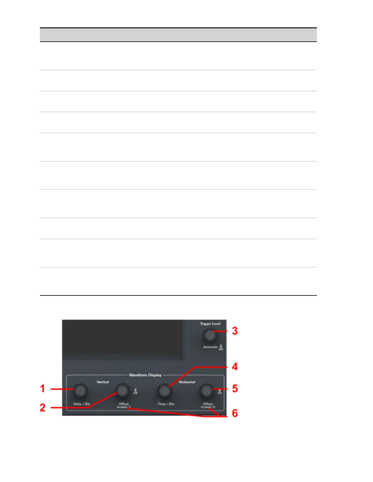
Using the Waveform Display Knobs
4 Using the Measurement Functions
150 Keysight N6705C Operating and Service Guide