SENS:DLOG:CURR:RANG 0.1, (@1)
SENS:DLOG:VOLT:RANG 5, (@1)
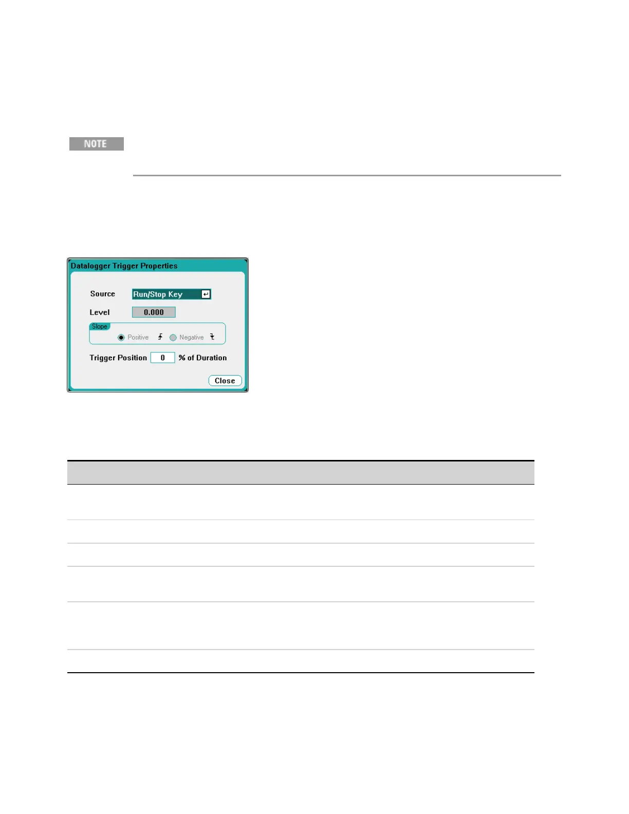
Data Logger Trigger
Once the Data Logger has been triggered, do not change the display to Scope View or
Meter View; otherwise Data Logger will stop.
From the front panel:
Select the Trigger button to configure the trigger properties. The Data Logger uses triggers to
synchronize itself with an external event.
The Source dropdown list lets you select a trigger source. The same trigger source will be used to
trigger all of the outputs that have been configured for data logging. Depending upon the selected
trigger source, you can trigger the Data Logger as follows:
Trigger Source Description
Voltage <1-4> level
Current <1-4> level
Triggers the Data Logger when the voltageor current of the corresponding output passes
through the specified level.
Run/Stop key Triggers the Data Logger when the Run/Stop key is pressed. This is the default trigger source.
Arb Run/Stop key Triggers the Data Logger when the Arb Run/Stop key is pressed.
OutputOn/Off key Triggers the Data Logger when any of the Output On/Off keys are pressed. Also applies to the All
Outputs On/Off key.
BNC Trigger In Provide a low-true signal to the BNC trigger input connector. Thesignal must have a minimum
pulse width of 2 microseconds. Selecting BNC Trigger In also enables any digital I/O pins con-
figured as Trigger Outputs (see Appendix C).
Remote Command Send a trigger command over oneof the three interfaces (i.e. *TRG).
If a trigger source is grayed out, it is unavailable. For example, current levels are not available as
trigger sources on outputs that have been grouped (paralleled). Note also that a trace must be turned
on for it to be used as a trigger source.
4 Using the Measurement Functions
154 Keysight N6705C Operating and Service Guide