Unite
®
Panel System - Electrical Installation
Assembly Instructions
Assemble units as described herein only. To do otherwise
may result in instability. All screws, nuts and bolts must be
tightened securely and must be checked periodically after
assembly. Failure to assemble properly, or to secure parts
may result in assembly failure and personal injury.
23
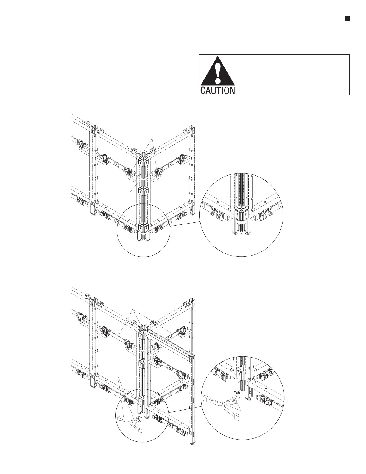
5-Horizontal Intersection 10-Wire Panel-to-Panel Jumper, 15 /”Length
(2-Way 90°, “L” Corner Panel Frame Intersection shown)
1
2
10-wire rigid
wireways
intersection 10-Wire
panel-to-panel jumper
(horizontal)(15 / length)
1
2
”
intersection 10-wire
panel-to-panel
jumper (horizontal)
(15 /”length)
1
2
6-Horizontal Intersection 10-Wire Panel-to-Panel Jumpers, 15 /”Length
(3-Way 90°, “T” Corner Panel Frame Intersection shown)
1
2
10-wire rigid
wireways
intersection 10-wire
panel-to-panel
jumpers (horizontal)
(15 /”length)
1
2
intersection 10-wire
panel-to-panel
jumper (horizontal)
(15 / length)
1
2
”