32
Unite
®
Panel System - Electrical Installation
Assembly Instructions
Assemble units as described herein only. To do otherwise
may result in instability. All screws, nuts and bolts must be
tightened securely and must be checked periodically after
assembly. Failure to assemble properly, or to secure parts
may result in assembly failure and personal injury.
infeed
conduit
11
/ -20 x 2 /
TF screw
44
”
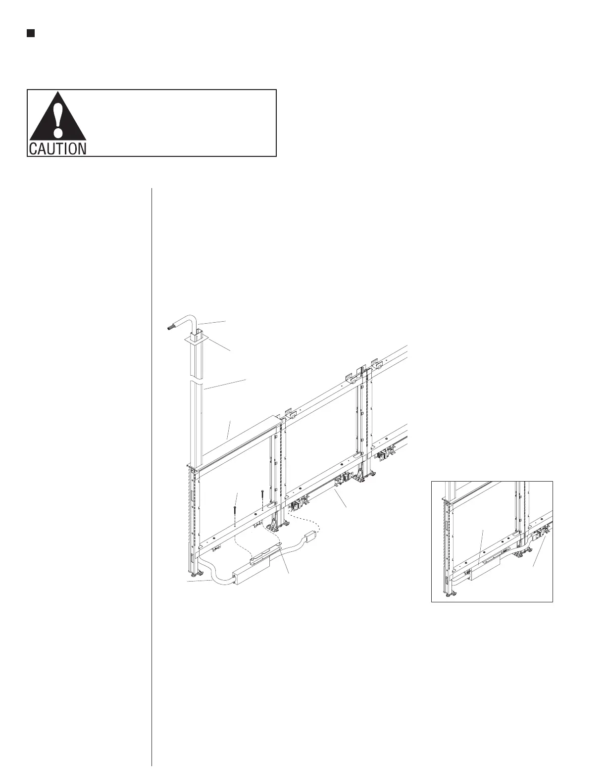
18-New York City Top Power Infeed
10-wire
top power infeed
(10-wire end)
top infeed
power pole
top infeed
panel trim cap
ceiling
trim cap
New York City infeed
mounting bracket
10-wire
rigid wireway
New York City Top Power
Infeed Installation (cont.)
2. Turn the New York City top
infeed assembly right side up as
illustrated and route the 10-wire
end of the infeed up through the
notch under the lower horizontal
rail and into the vertical channel
of the panel frame upright and let
sit. Position the New York City
infeed mounting bracket under
the horizontal frame as illustrated
and secure using two
1
/
4
-20 x 2
1
/
4
” thread-forming
screws through the horizontal
frame and into the New York City
infeed mounting bracket
(Figure 18).
Note: It is easier to plug the
power infeed into the rigid
wireway if the wireway is
disconnected from the wireway
mounting brackets first.
3. Route the plug-end of the power
infeed around the panel vertical
rails, and press the plug into the
adjacent panel rigid wireway,
snapping in to secure (Figure 18
& Detail K).
4. Refer back to “10-Wire Top Power
Infeed Installation”, page 29,
steps 1 through 9 for installation
of power pole to ceiling and to
top infeed trim cap (Figure 18 &
Detail K)
Note: The power infeeds are to
be connected to the power source
by a qualified electrician who
must follow all state and local
codes at the building site and
check the electrical integrity of
the finished system.
New York City
infeed assembly
10-wire rigid
wireway