Unite
®
Panel System - Gallery Panel Installation
Assembly Instructions
Assemble units as described herein only. To do otherwise
may result in instability. All screws, nuts and bolts must be
tightened securely and must be checked periodically after
assembly. Failure to assemble properly, or to secure parts
may result in assembly failure and personal injury.
39
End-of-Run Dual-Sided
Two-Piece Gallery Panel
Installation (cont.)
Note: Make sure the top and bottom
of both two-piece gallery panels are
flush with each other.
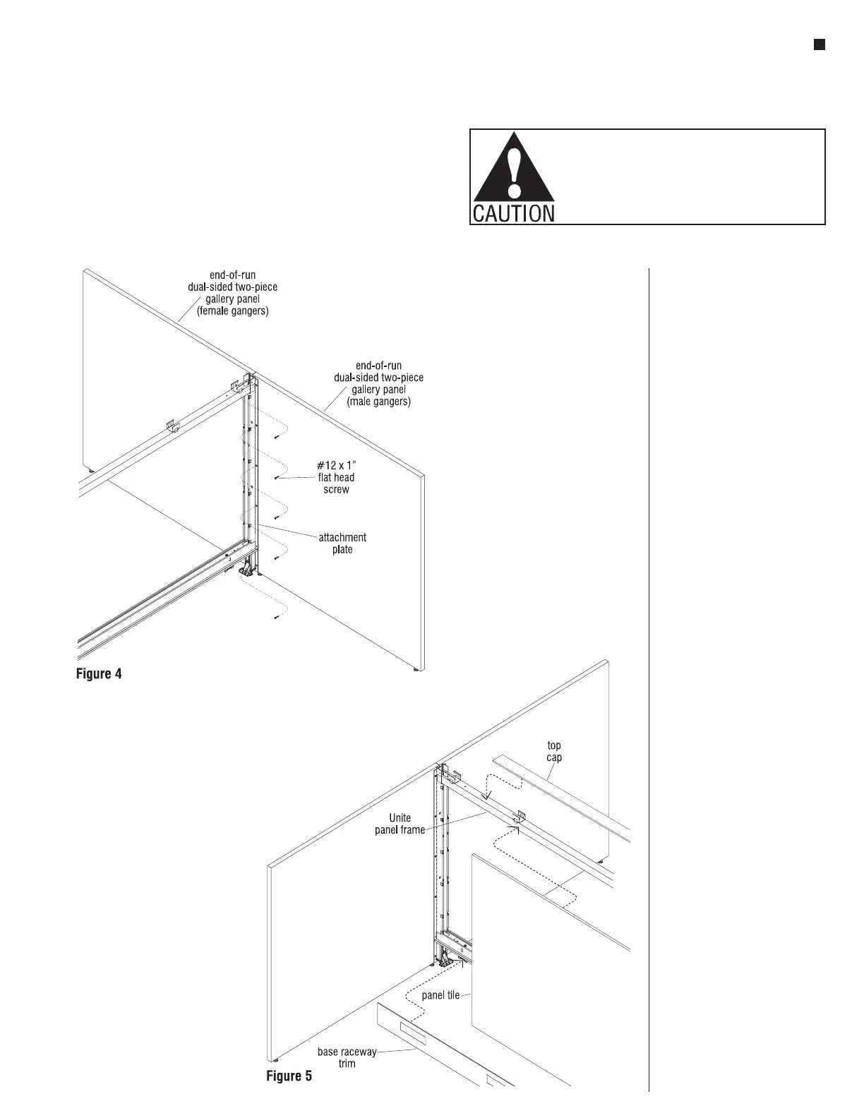
7. Secure the attachment plate to the
second (male ganger) two-piece
gallery panel using the #12 x 1"
flat head screws into all remaining
holes of the attaching plate
(Figure 4).
8. Gallery panel glides should be
checked and adjusted again at
this point. Measure the distance
from the bottom of the Unite panel
raceway trim, or lifted foot shroud
down to the floor. Adjust the
glide from the bottom edge of the
gallery panel the same distance.
This step may require attaching a
raceway cover or foot shroud to
the Unite panel frame (Detail C).
9. Install Unite panel run tiles, top
cap & base raceway trim. See Tile
Installation section starting on
page 45 (Figure 4).
 Loading...


