ASSEMBLY INFORMATION
9
113
EN
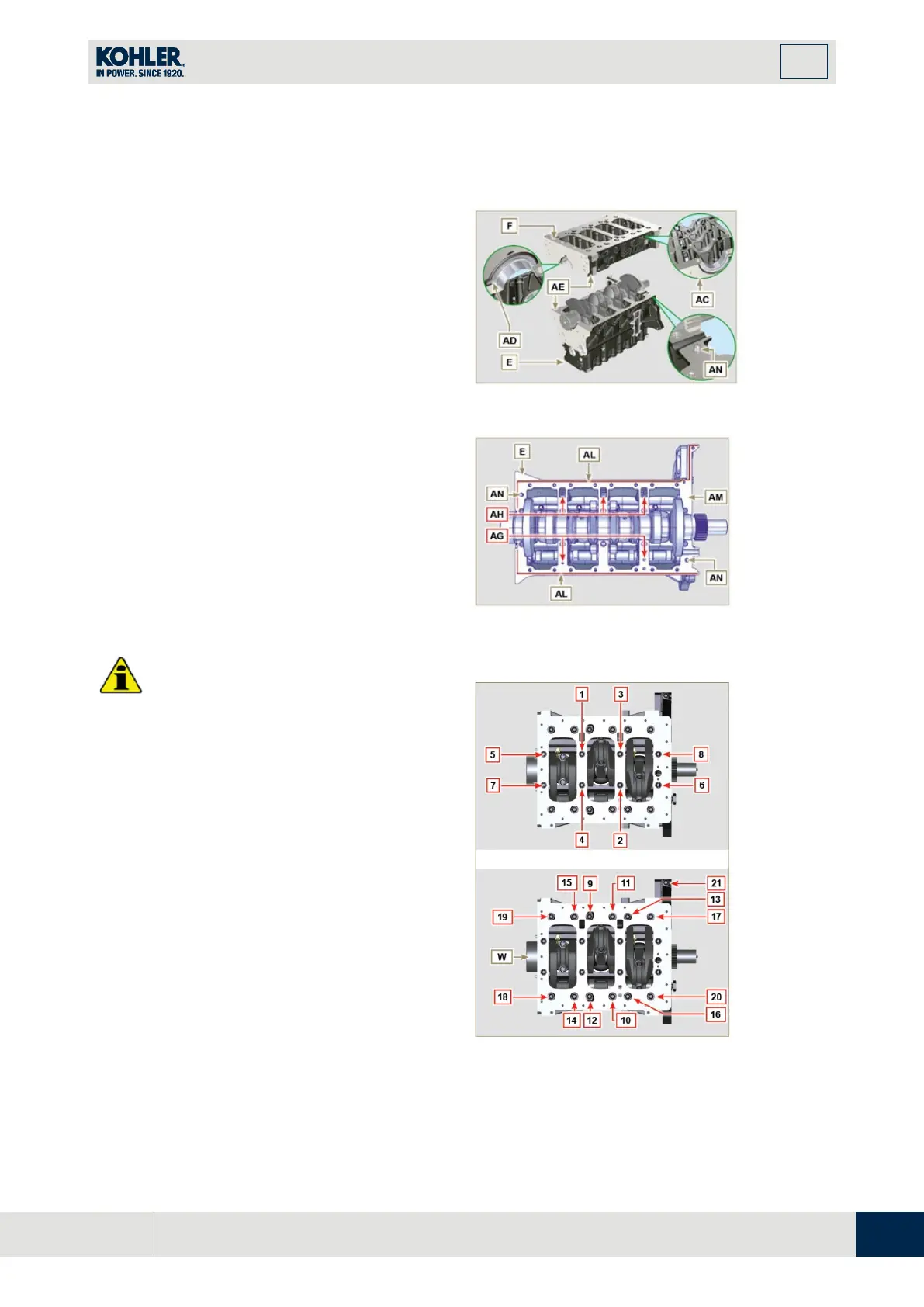
Insert the 2 shoulder half-rings K,
between the crankshaft W and the upper
crankcase E (AB detail).
1.
Check that the crankshaft half-bearings
are mounted correctly on the lower
cr
ankcase F (AC detail).
2.
Assemble the 2 shoulder half-rings AD
onto the lower crankcase F applying two
drops of oil to keep them in their seat.
3.
Check that the coupling surfaces AE ar
e
f
ree from dirt and grit.
Fig 9.7
4.
Spread a bead of Loctite 5660 (rif. AL) of
approx 1 mm thickness on the sur
face
AM of the upper crankshaft half C being
careful not to block the oil feed grooves
AG and the return oil sump AH.
5.
Join the two crankshaft halves E and F
observing the guide pins AN.
•
Failure to follow the bolting procedures
compromises the functionality of the
engine and can cause damage to people
a
nd property.
6.
Tighten the fastening screws strictly
following the sequence and the tightening
torque indicated.
Tightening sequence for 3 cylinders
Tightening Screws Torx M12x1,25 (from
the n° 1 to the n° 8):
CYCLE 1 - with a torque of 40 Nm;
CYCLE 2 - with a torque of 70 Nm;
CYCLE 3 - with a torque of 120 Nm.
Tightening Screws Torx M8 (from the n° 9 to the
n° 21):
CYCLE 4 - with a torque of 20Nm;
CYCLE 5 - with a torque of 35 Nm;
7.
Perform the operations described in Par.
8.4.2.
Fig 9.9

 Loading...


