8
INFORMATION ABOUT OVERHAULING
EN 104
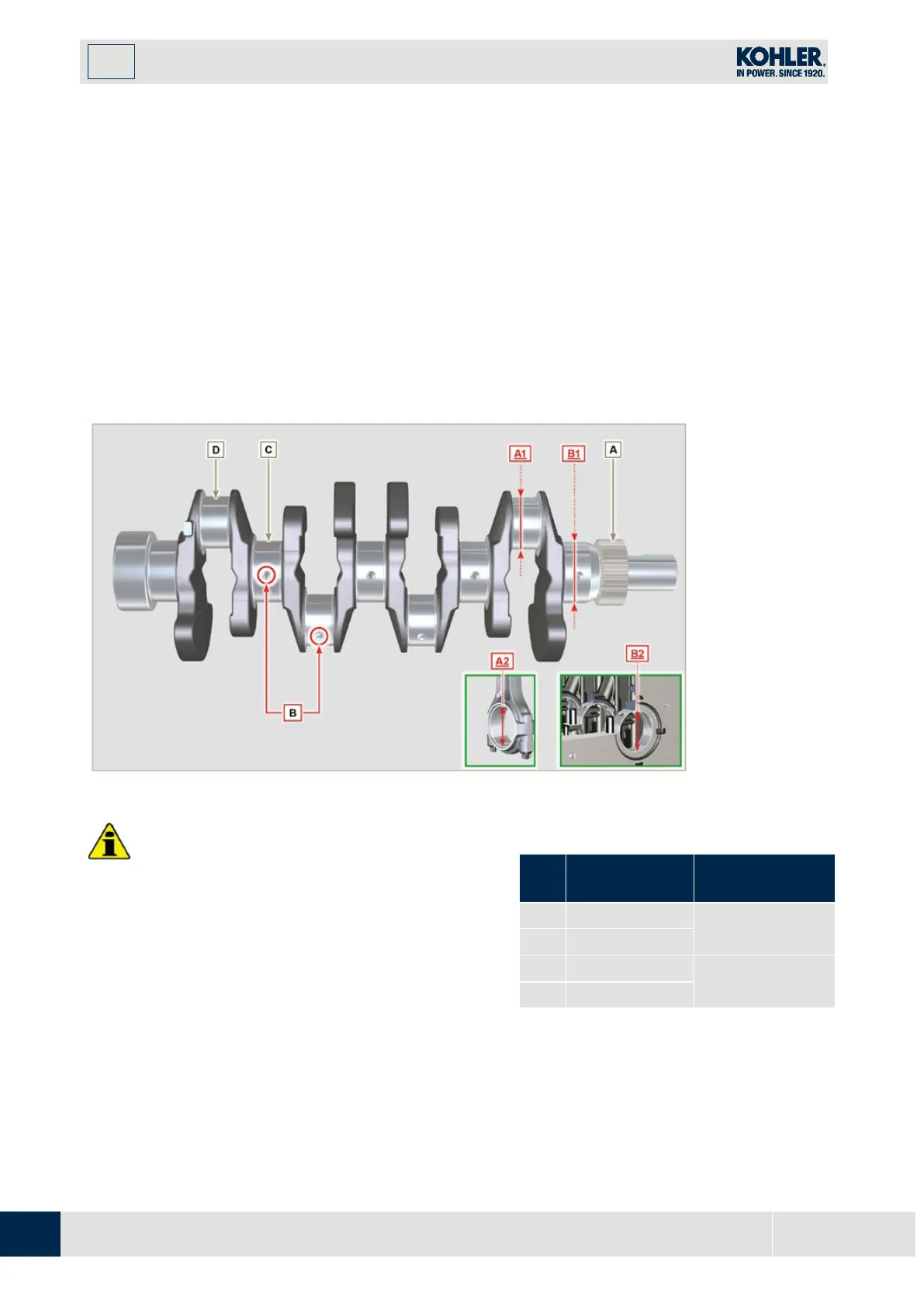
Insert the pipe cleaner into all lubrication ducts
B
and blow compressed air to free them completely from
any dirt residues.
Check the state of wear and integrity of journals
C
and connecting rod
D
.
P
erform the operations described in
Par. 9.3.1
, perform the operations described in
Par. 9.3.6
- except
Points
2, 4, 9 and 10
.
Measure the crank pins
A1
with a micrometer, and using a dial gauge measure the internal diameter of the
connecting rod half-bearings
A2
.
Measure the main journals
B1
, with a micrometer, and using a dial gauge measure the internal diameter of
the crankshaft half-bearings
B2
.
If the values described in
Tab. 8.5
do not correspond, proceed with grinding all gudgeon pins
A1 and B1
.
Gear A on the crankshaft is timed by a key, assembly of gear A on the shaft occurs after heating at a
stabilized temperature of +180° C for 5 mins.
•
The crankshaft and connecting rod must be
replaced every time they are assembled to prevent
seizure, as they are made of special lead-free
m
aterial.
•
The MAX allowed value of wear for A1 and A2 is
0.120 mm.
•
The MAX allowed value of wear for B1 and B2 is
0.120 mm.
•
To grind the crankshaft, a decrease in diameter o
f
the
halfbearings and connecting rod is provided
for at 0.25 mm and 0.50 mm, to grind gudgeon
p
ins A1 and B1, measure the values of diameters
A2 and B2 by assembling the decreased half-
bearings, define the diameter to grind of pins
Tab 8.5 Connecting rod and journal
diameter
REF.
(mm)
CLEARANCE
VALUE (mm)
0.035 - 0.085
0.035 - 0.102

 Loading...


