INFORMATION ABOUT OVERHAULING
8
111
EN
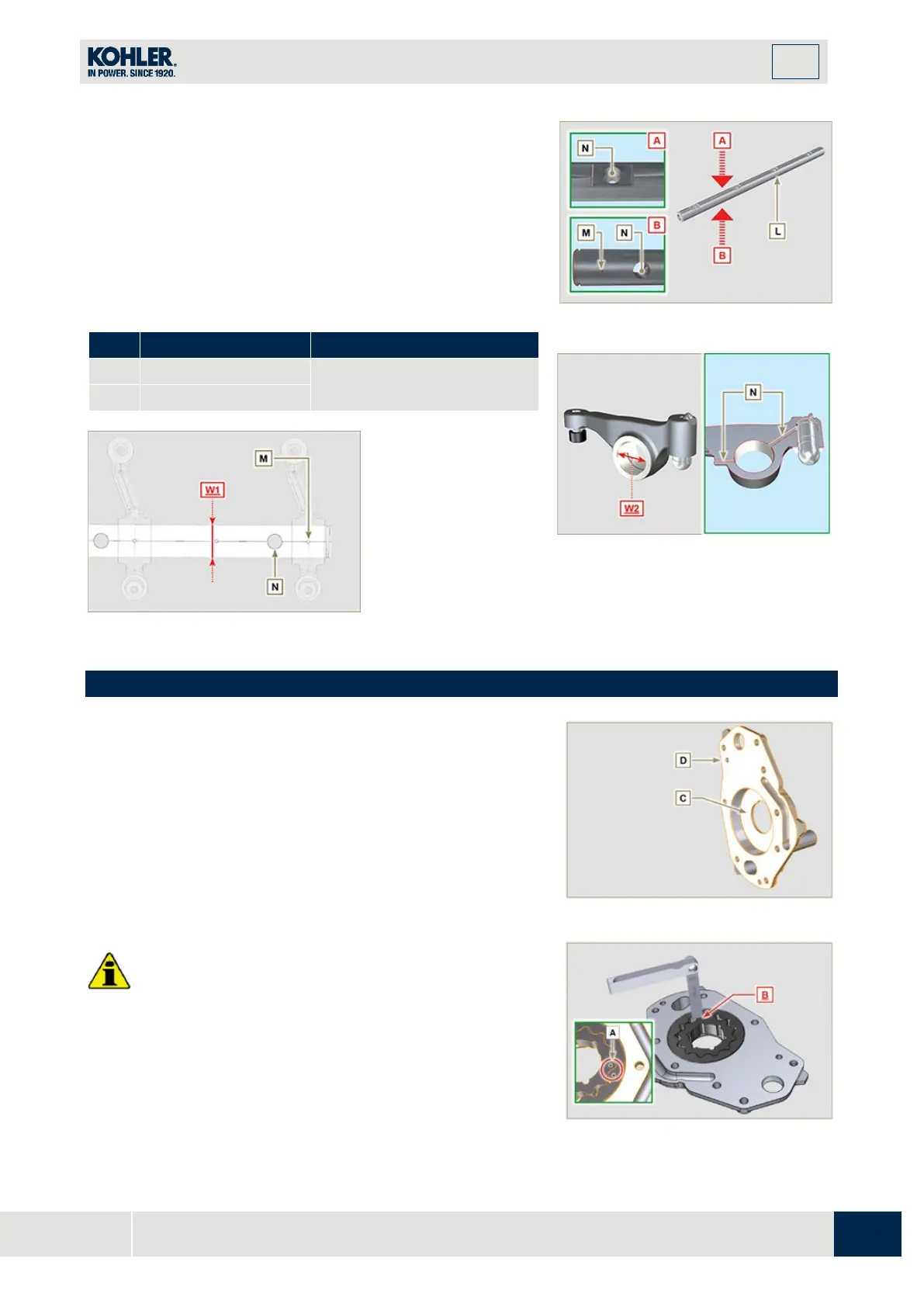
Measure values W1 in correspondence with holes M located on
rocker arm gudgeon L (seen from B in Fig. 8.25).
Measure values W2 (Fig. 8.27).
Based on the values measured, calculate the clearance between
W1 and W2, which is to observe the values in Tab. 8.12.
Check that all oil pipes N and M are free from impurities or
obstructions.
T
ab 8. 12
0.035 - 0.076
Fig. 8.26
Fig 8.25
Fig 8.27
8.7 Oil pump check
8.7.1 Dimensional and visual check
Perform the operations described in
Par.7.8.1 and Par.7.8.4.
Measure clearance value B between the rotor teeth, the value of
allowable wear is MAX 0.28 mm.
Clean all the components thoroughly, check that the work
surfaces C of the rotors and pump body are not worn.
Important
•
Should the results from checks carried out not be i
n
acco
rdance with the conditions described, replace th
e
timing system carter together with the oil pump.
On assembly, references A must be visible.
Fig 8.28

 Loading...


