EasyManuals Logo

Kohler KDI 2504TM Workshop Manual

Kohler KDI 2504TM
184 pages
To Next Page IconTo Next Page
To Previous Page IconTo Previous Page
Page #26 background imageLoading...
Page #26 background image
2
TECHNICAL INFORMATION
EN 26
2.10 Lubrication circuit
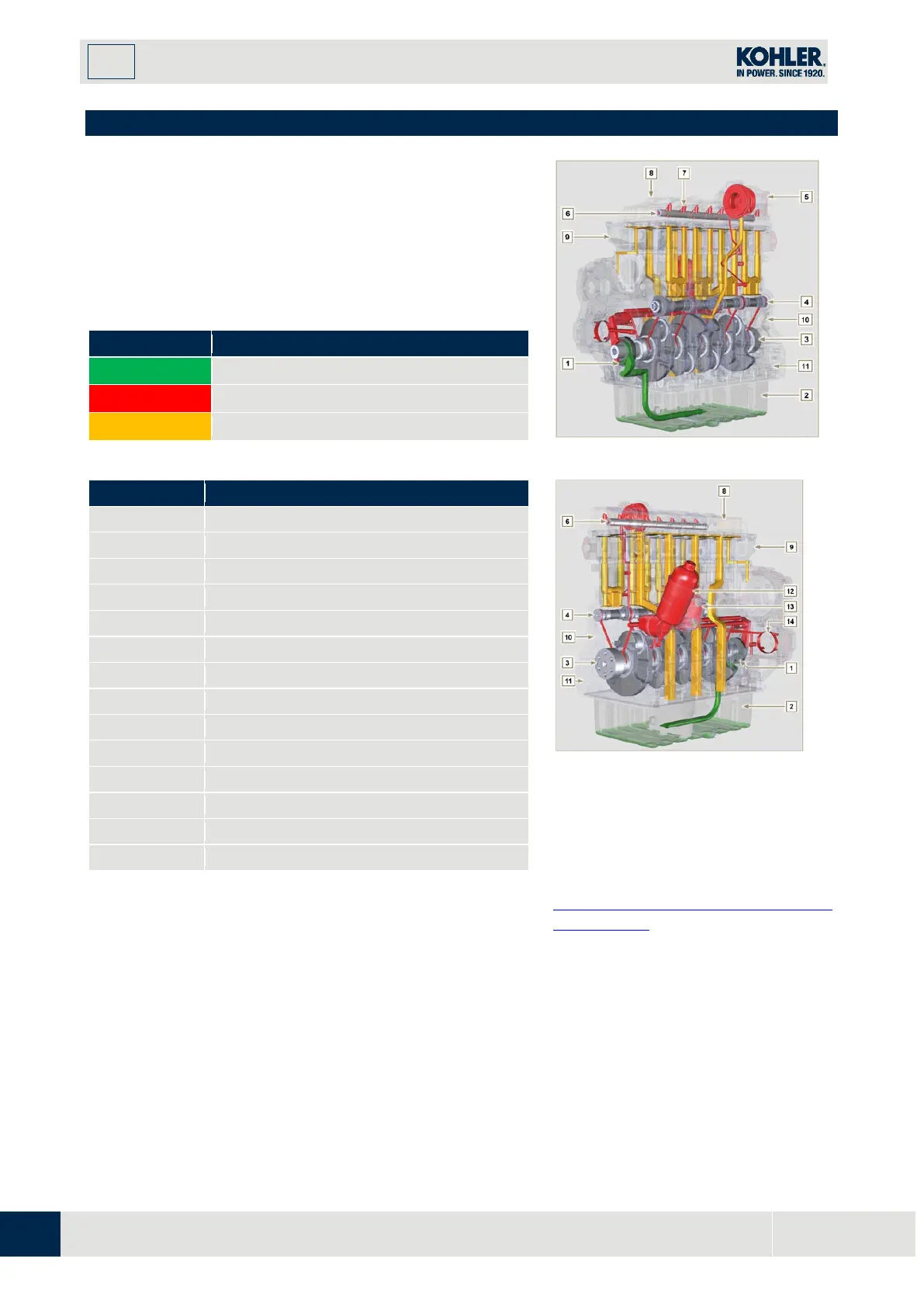
2.10.1 Lubrication circuit diagram
The oil pump is driven by the crankshaft on the timing system
side.
On the parts of the systems shown in green on In the parts in
green, the oil is in intake, in the parts in red, the oil is under
pressure and in those in yellow the oil is returning towards the
oil sump 2 (not under pressure).
T
ab 2.19
COLOUR
DESCRIPTION
Oil in intake
Oil under pressure
Oil returning to the oil sump
Tab 2.20
POS.
DESCRIPTION
1
Oil pump rotors
2
Oil sump
3
Crankshaft
4
Camshaft
5
Turbocharger
6
Rocker arm pin
7
Hydraulic tappets
8
Rocker arm cover
9
Cylinder head
10
Upper crankcase
11
Lower crankcase
12
Oil filter
13
Oil Cooler
14
Housing
Fig 2.13
F
ig 2.14
NOTE
: Click by side to play the procedure.
https://www.youtube.com/embed/Ig3Xo
sQ8h0s?rel=0

Table of Contents

Other manuals for Kohler KDI 2504TM

Questions and Answers:

Question and Answer IconNeed help?

Do you have a question about the Kohler KDI 2504TM and is the answer not in the manual?

Kohler KDI 2504TM Specifications

General IconGeneral
BrandKohler
ModelKDI 2504TM
CategoryEngine
LanguageEnglish

Related product manuals