INFORMATION ABOUT OVERHAULING
8
105
EN
observing the clearance indicated in Tab. 8.5.
•
La Tab. 8.5 riporta i valori dimensionali solo per
i
c
omponenti nuovi.
8.4.2 Checking the axial clearance of the crankshaft
P
erform the operations described in
Par. 9.3.5 and 9.3.6
.
Using a dial gauge, measure the axial shift of crankshaft
E
.
Axial shift must be a
MIN
of 0.18 mm and
MAX
0.38 mm..
If the values measured do not correspond, replace
shoulder rings
D
.
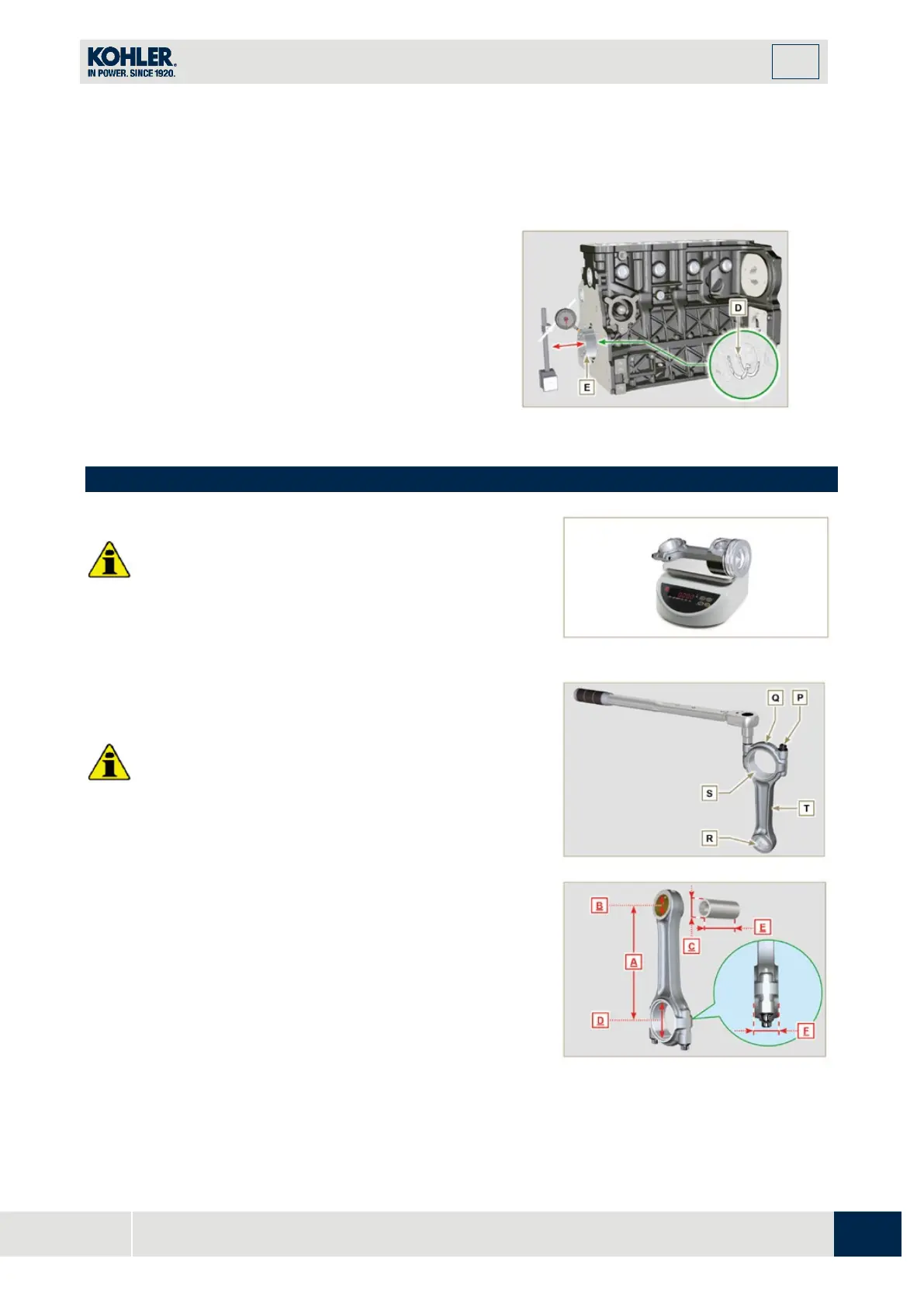
8.5 Connecting rod - piston assembly
Important
•
I
n case of replacement, the connecting rods and pistons
must always be replaced for all cylinders.
8.
5.1 Connecting rod dimensions check
Important
•
Before assembling the connecting rod and pistons (Par.
9.3.7 e 9.3.8), check that the difference in weight
between the complete connecting rod and piston units
do not exceed 8 gr to prevent weight imbalances during
rotation of the crankshaft and consequent damage.
•
Mark some references on the connecting rods, caps Q,
pistons and gudgeon pins to prevent unintentionally
confusing the components during assembly. Failure to
do this may result in engine malfunctions.
•
Connecting rod half-bearings S must be there with eac
h
a
ssembly.
Check that the contact surfaces are perfectly clean and intact.
Assemble the connecting rod cap Q to the connecting rod with
the half-bearings S and tighten capscrews P (tightening torque
at 25 Nm).
With a dial gauge, measure diameters B and D.
The MAX allowed value of wear for B and D is 0.06 mm.
Fig 8.11
Fig 8.12
Fig 8.13

 Loading...


