11
INFORMATION ABOUT OPTIONAL
COMPONENTS
EN 152
washers H, the screws A and the cable B.
2.
Secure the flange H with the screws A (tightening torque
at 22 Nm).
3.
Secure the earth cable B with the nut J and the relevant
washer on the heater E.
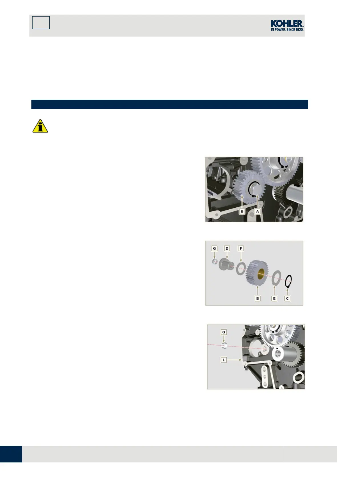
11.3 Idler gear (for 3rd / 4th PTO)
•
Before proceeding with operation, read Par. 3.3.2.
11.3.1 Disassembly
1.
Undo the screw A and remove the gear unit B.
Fig 11.8
2. Remove the retainer ring
C
from the seat of the pin
D
.
3. Remove the shoulder washer
E
, the gear
B
, the shoulder ring
F
and the bushing
G
from the pin
D
.
Fig 11.9
11.3.2 Assembly
1.
Fit into the pin D :
- The shoulder ring F (of least thickness)
- The gear B
- The shoulder ring E
- The retainer ring C.
2.
Insert the bushing G on the crankcase L.
Fig 11.10

 Loading...


