ASSEMBLY INFORMATION
9
133
EN
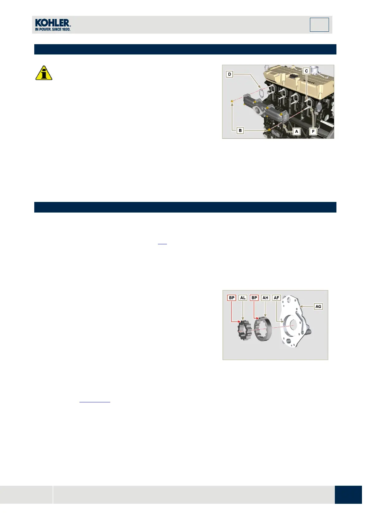
9.10 Exhaust manifold assembly
•
Replace the self-locking nuts B and the metal gaskets
D between the manifold and the cylinder head every
time they are assembly.
•
In the event of mounting the studs C, fix (25 Nm
tightening torque) with Loctite 2701 on the thread.
1.
Check that the contact surfaces F are free from
impurities.
2.
Insert the gaskets D and E on the studs C.
3.
Position the manifold A on the studs C.
4.
Fix the manifold A on the cylinder head by tightening
the self-locking nuts B (tightening torque of 25 Nm).
Fig 9.71
9.11 Lubrication circuit assembly
9. 11.1 Assembly oil mist separator unit
1.
Follow operations 1, 3, 4, 6, 7 and 8 of Par. 6.8.2.
9. 11.2 Oil Cooler and oil filter Unit Assembly
1.
Follow operations of Par. 6.6.2 - 6.
6.3.
N
OTE:
Carry out the checks described in
Par. 8.7
before
proceeding with the following operations.
1.
Check that all contact surfaces between AL, AH, AF
,
AG
and AN are free of impurities – scratches - dents.
2.
When assembling, do not use any type of gasket
between AG and AN.
3.
Thoroughly lubricate the seat of the rotors AF on the oil
pump crankcase AG and the two rotors AH and AL.
4.
Insert, inside the seat AF, the 2 rotors (in sequence) AH
and AL, respecting the reference BP as the picture. (or
re
fer to Par. 2.10.2
).
Fig 9.73

 Loading...


