INFORMATION ABOUT OPTIONAL
COMPONENTS
11
165
EN
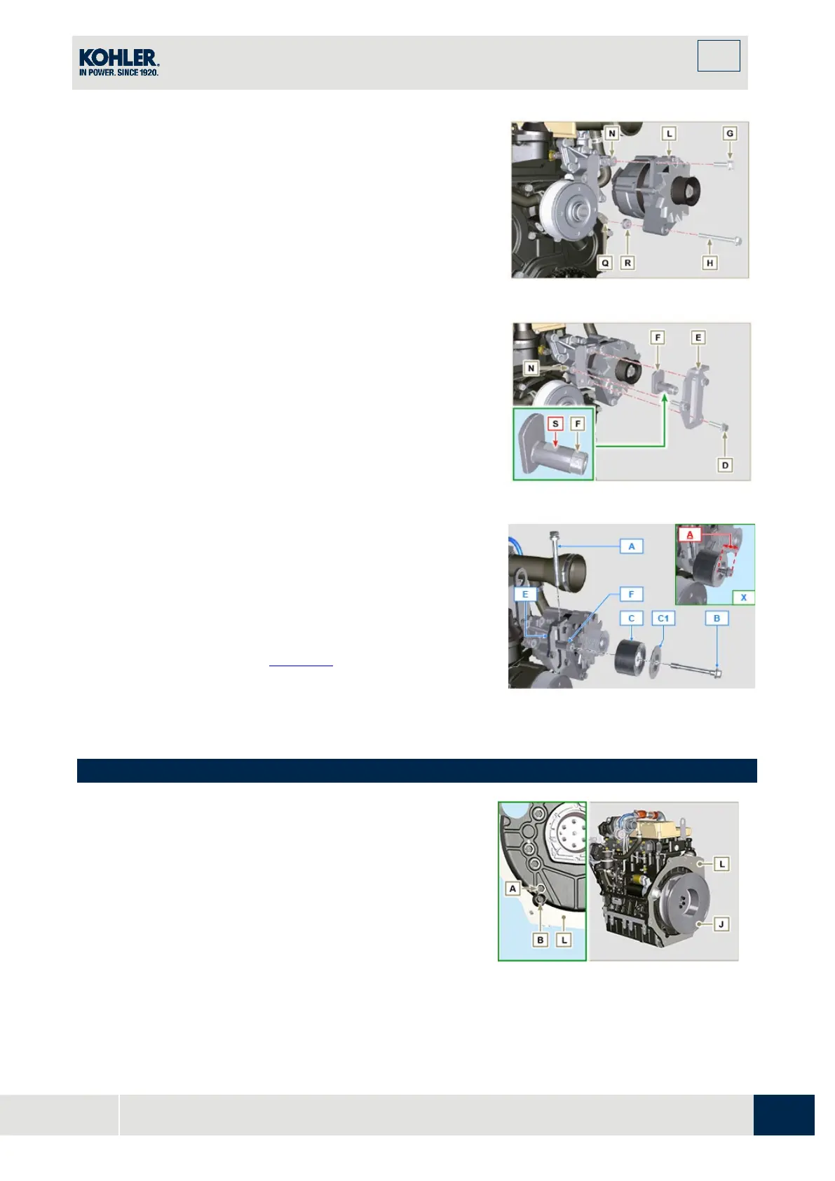
2.
Insert the screw H into the fixing hole on the alternator L.
3.
Insert the spacer R on the screw H (between the
alternator and crankcase).
4.
Tighten the screw manually H onto the crankcase Q.
5.
Orientate the second fixing hole of the alternator L wit
h
t
he hole of the bracket N, secure the alternator L using
the screw G (tightening torque at 25 Nm) onto the
bracket N and then the screw H (tightening torque at
25
Nm)
.
6.
Insert the pin F in the plate slot E.
7.
Orientate the pin F with the surface S (support for screw
A) upwards.
8.
Secure the plate E using the screws D on the bracket N
(tightening torque at 25 Nm).
Insert the screw
in the plate
and pulley
.
10.
Manually tighten the screw B onto the pin F up to the
stop; Undo the screw B again by one turn.
NOTE: The screw B must protrude by about 32 mm (A) from the
surface of the tightening pulley C (see detail X).
11.
Install the new belt H (Fig. 11.43).
12.
Tighten the screw A onto the plate E up to the stop o
n
the
pin F.
13.
Perform the operations point 6 to 8 of Par. 11.9.
Fig 11.52
11.11 Oil sump with supporting structure
11.11.1 Flywheel (J) disassembly
1.
Execute the operations described in Par. 7.11.1.
11.11.2 Plate/flange housing (L) disassembly
1.
Loosen supplementary capscrews A and B.
2.
Execute the operations described in Par. 7.11.2.
3.
Remove housing or plate L.
Fig. 11.53

 Loading...


