11
INFORMATION ABOUT OPTIONAL
COMPONENTS
EN 166
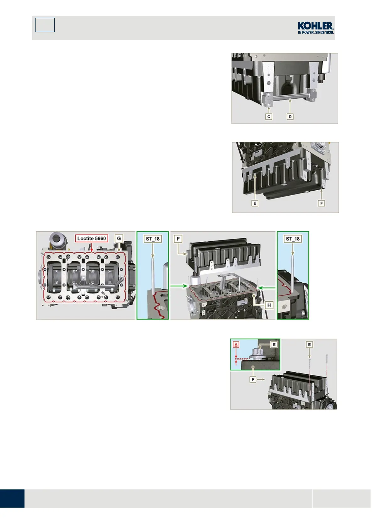
11.11.3 Oil sump disassembly
1.
Execute the operations described in Par. 5.2.
2.
Loosen capscrews C and remove bypass tube D.
3.
Loosen capscrews E and remove oil sump F.
Fig. 11.54
11.11.4 Oil sump assembly
1.
Make sure contact surfaces G of oil sump F an
d
cr
ankcase H have no impurities.
2.
Apply a sealing bead of approximately 2.5 mm (Loctit
e
5660) onto surface G of crankcase H.
3.
Place oil sump F onto crankcase H in correspondence
with the fastening holes (use tool ST_18).
Fig. 11.55
Fig. 11.56
Apply capscrews E into the fastening holes and use
torque at 10 Nm.
5.
Loosen capscrews E, leaving approximately 1 mm leeway
(position A) between the neck surface of capscrews E
and oil sump F.
6.
Place flange housing or plate L onto crankcase H,
complying with centring tap pins M.
7.
Using 2 capscrews A, fasten housing or plate L onto
crankcase H (tightening torque at 20 Nm).
8.
Using 2 capscrews A, fasten housing or plate L onto oil
sump F (tightening torque at 20 Nm).
Fig. 11.57

 Loading...


