INFORMATION ABOUT OPTIONAL
COMPONENTS
11
167
EN
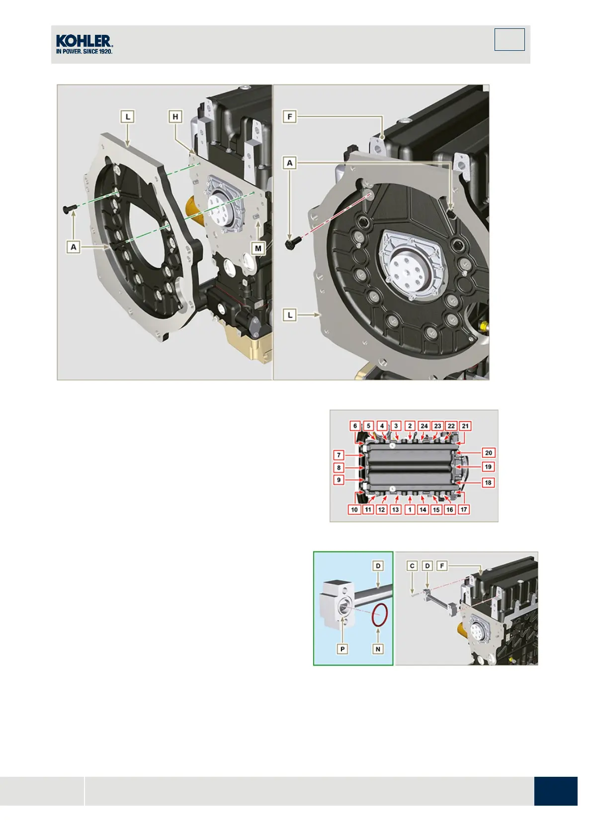
Fig. 11.58
9.
Fasten oil sump F by tightening capscrews E an
d
s
trictly following the order shown in Fig. 11.59
(tightening torque at 20 Nm).
10.
Loosen capscrews A and remove housing or plate
L (Fig. 11.58).
11.
Fasten oil sump F by tightening capscrews E an
d
s
trictly following the order shown in Fig. 11.59
(tightening torque at 47 Nm).
Loosen the screw 1 again and tighten it to 47 Nm.
Fig. 11.59
12.
I
nsert gaskets N into seats P of bypass tube
D.
13.
Fasten bypass tube D onto oil sump F using
capscrews C (tightening torque at 10 Nm).
Fig. 11.60

 Loading...


