INFORMATION ABOUT OPTIONAL
COMPONENTS
11
151
EN
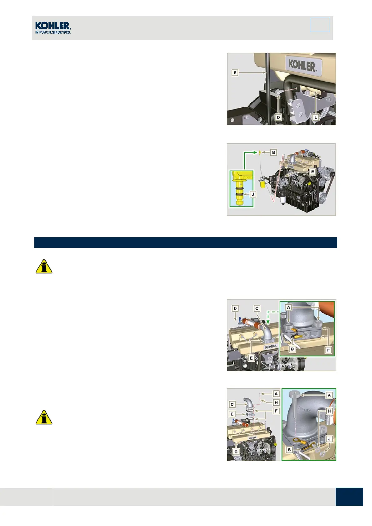
3.
Tighten the oil dipstick hose E using the screw D on th
e
m
anifold L (Tightening torque of 10 Nm).
Fig 11.4
NOTE:
Check the integrity of the gaskets
J.
4.
Insert the dipstick B inside the hose E.
11.2 Heater (replacement)
•
Before proceeding with operation, read Par. 3.3.2.
11.2.1 Disassembly
1.
Undo the screws A and the relevant washers and
remove the earth cable B.
2.
Remove the flange C and the manifold D.
3.
Remove the heater E and the relevant gaskets F.
11.2.2 Assembly
Important
•
Always replace gaskets F, with each assembly.
1.
In sequence, fit the manifold G with the gasket F, the
new heater E, the second gasket F, the flange C, the

 Loading...


