ASSEMBLY INFORMATION
9
125
EN
9.7 Cylinder head unit assembly
Important
•
Carry out the checks described in Par. 8.6.4 befor
e
p
roceeding with the following operations.
•
Always replace gasket A with every assembly
•
Lubricate the gaskets A on the inside.
1.
Fit the oil seals A on the valve guides B using the tool
ST_08.
Fig 9.38
9.7.2 Injector sleeves
( )
1.
Insert the seals C in the seats of the sleeve D.
2.
Insert the seal E with the convex side facing upward
at the base of the sleeve D.
3.
Lubricate the gaskets C.
4.
Insert and carefully screw the sleeve D into the seat
o
f the head F.
NOTE: The sleeve D must not protrude above the surface of
the head BF.
5.
Clamp the sleeve D (tightening torque at 30 Nm).
Fig 9.39
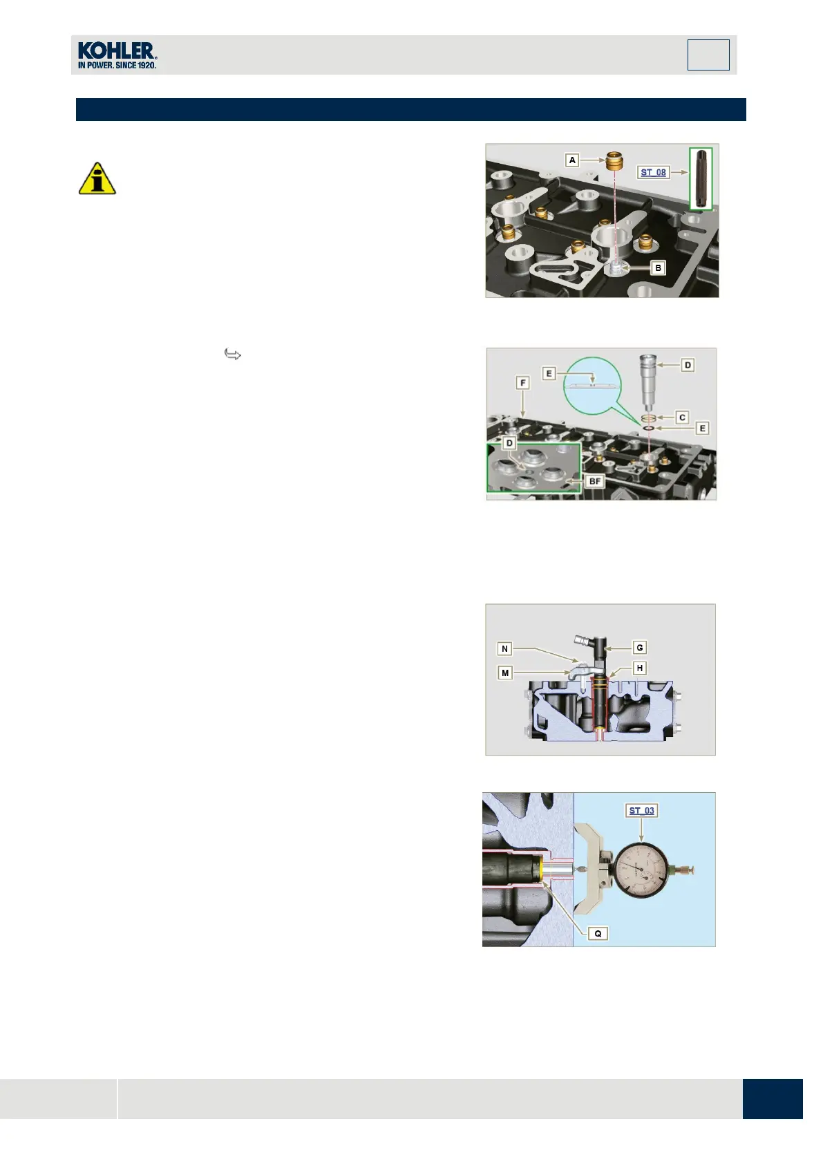
9.7.3 Injectors projection
1.
Insert the injector G inside the sleeve H.
2.
Mount the injector fixing bracket M and secure it wit
h
the screw N, without performing the calibration.
3.
Check protrusion of injectors by means of the tool
ST_03 (Fig. 9.44), check the projection of the injector,
which must range between 1.68 ÷ 2.42 mm.
NOTE : if the value detected does not correspond, replace
gasket Q with a different thickness.
Fig 9.40

 Loading...


