9
ASSEMBLY INFORMATION
EN 124
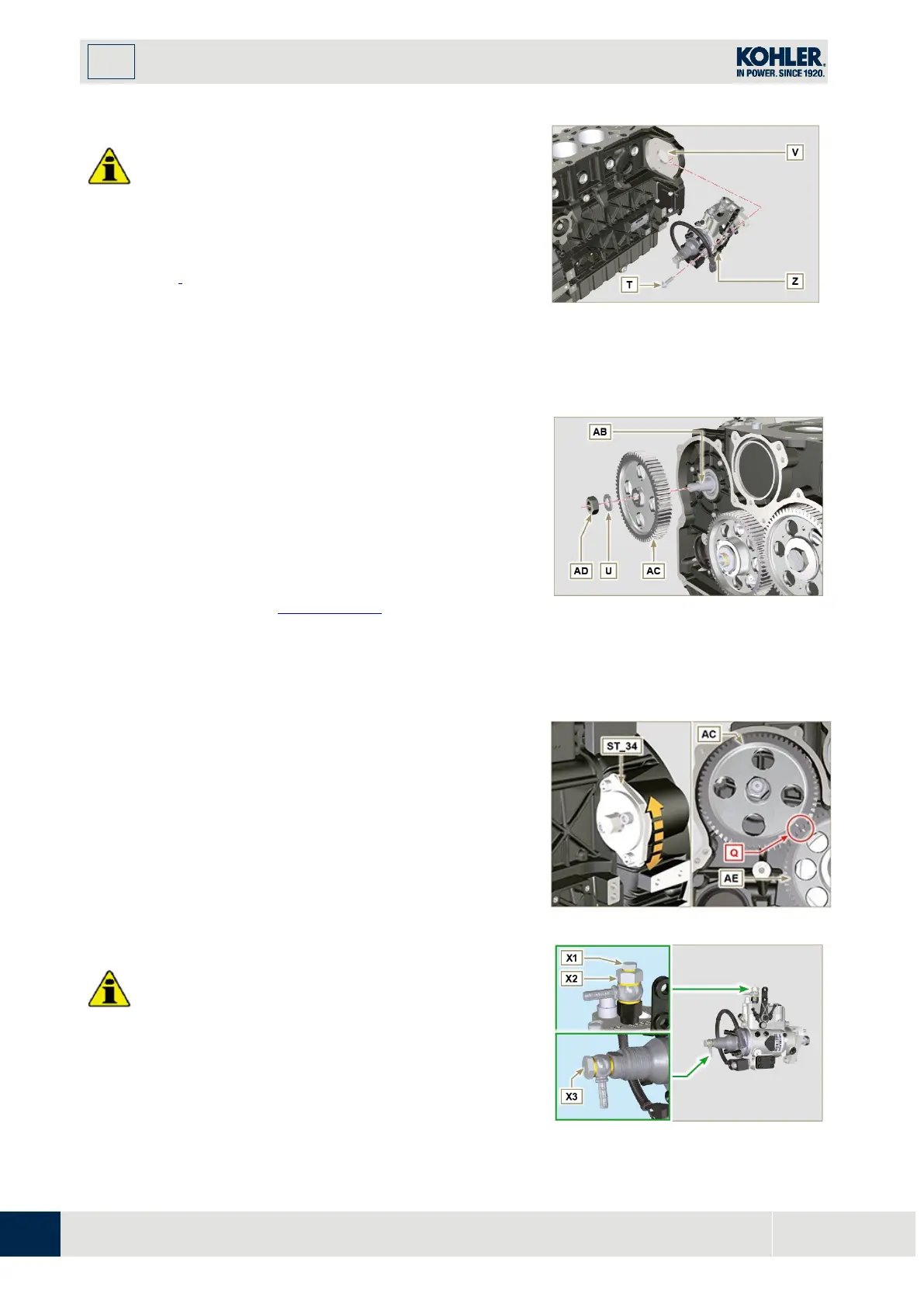
Important
•
Always change screws T with new ones or alternatively
apply Loctite 270 (Fig. 9.34) to the threads.
1.
P
erform the operations described in the warning in Par.
6.1.5.
2.
Place a dial gauge to detect the TDC on piston N° 1,
then bring the indicator of the dial gauge to 0.
NOTE
: During the detection phase of the TDC, check that
cylinder N°
1
is in compression phase (align the notches
W
as
in
Fig. 9.33
).
Fig 9.34
3.
By means of the identified pump code, refer to Tab. 6.1
to know the advance degrees and the corresponding
value to lower the piston.
4.
Mount tool ST_34 in the seat of starter motor H (Fig.
9.29) and fix it with two motor fixing screws.
5.
Having identified the value to lower the piston, rotate
the crankshaft anti-clockwise by going beyond the
value described in Tab. 6.1, once again, rotate th
e
cr
ankshaft clockwise stopping at the correct advan
ce
va
lue by using tool ST_03 - ST_34
.
6.
Lock the ST_34, ensure that the crankshaft does no
t
r
otate, which would alter the correct advance value.
If this happens, repeat the instructions described in
p
oints 4, 5 and 6.
Fig 9.35
7.
Fix pump Z into housing V by means of screws T (Fig.
9.34 - tightening torque at 25 Nm).
8.
Position the gear AC onto shaft AB of the pump.
NOTE:
You are not required to respect the reference
Q
gear
AE
(
Fig.
9.36
).
1.
Insert washer U and tighten nut AD (tightening torque
at 70 Nm).
Important
•
In the event of assembling screw X1 (tightening torque
at 10 Nm).
•
In the event of assembling screws X2 and X3
(tightening torque at 2 5 Nm).
Fig 9.36
Fig 9.37

 Loading...


