INFORMATION ABOUT OPTIONAL
COMPONENTS
11
163
EN
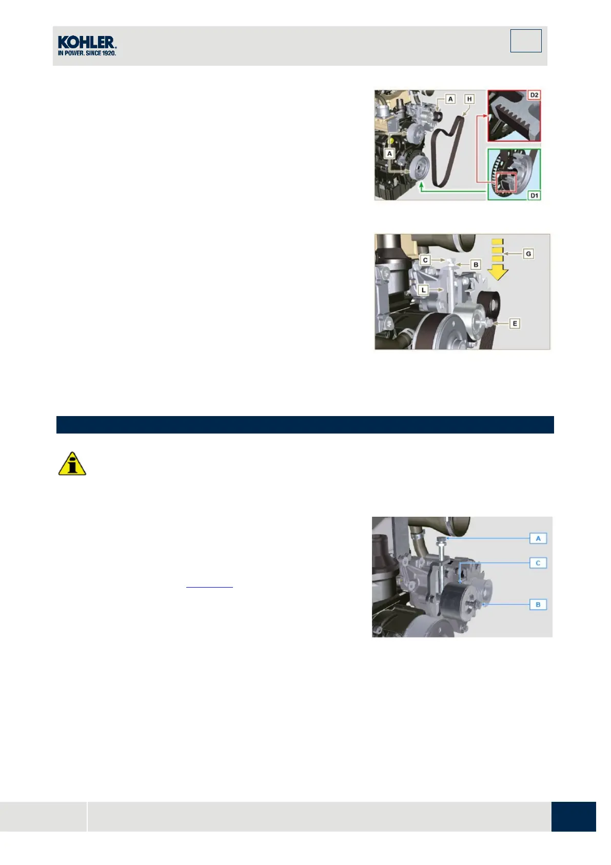
4.
Remove the V-Belt H and install the new one.
NOTE: Ensure that the internal profile of belt H is properly
inserted into the grooves of the pulley A (as illustrated in D1 e
D2).
5.
Tighten capscrew C, to shift gudgeon D fully to the
bottom of the grooved guide.
6.
Tighten capscrew E (tightening torque at 45Nm).
7.
Hold the screw C still with a key, and tighten the screw B
on the plate L to secure the screw C (tightening torque
at 45Nm).
8.
Check, in point P (Fig. 11.8),the tension of the belt.
Check by the appropriate tool that at point p the tensio
n
v
alue is between 149 and 196 Hz.
NOTE: After the engine has been in operation for around 15
Fig 11.44
11.10 Tightening pulley and alternator for Poly-V belt
•
Before proceeding with operation, read Par. 3.3.2.
11.4.1 Disassembly
1.
Perform the operations from point 1 to 3 of Par. 11.9.
2.
R
emove the belt H (Fig. 11.43).
3.
Undo and remove the screw A.
4.
Fully undo the screw B and remove the tightening pulley
C.

 Loading...


