ASSEMBLY INFORMATION
9
137
EN
- Q and S;
- Q and H.
Fasten the fuel outlet pipe Q with the fittings
R on the turbo-compressor H and on the
crankcase S (tightening torque of 15 Nm).
9.
Follow operations 4 and 5 of Par. 6.1.9.
9.14 Coolant circuit assembly
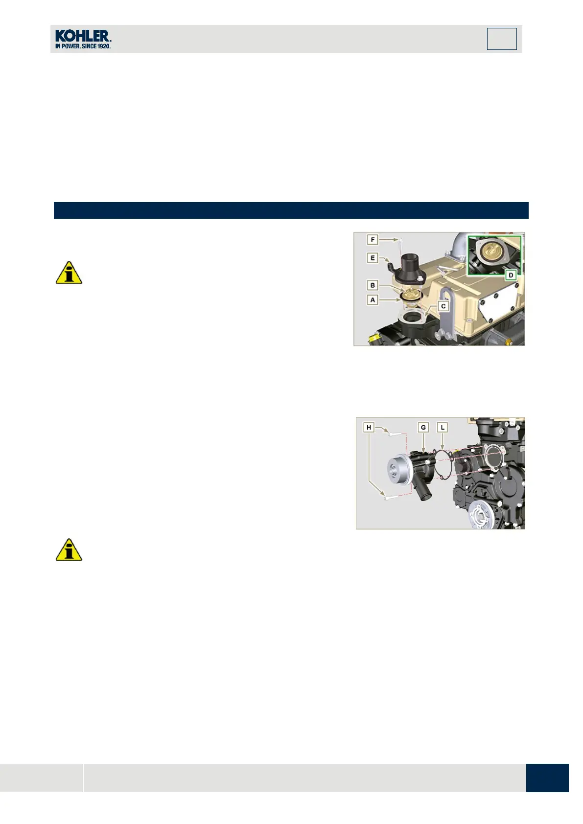
9.14.1 Thermostatic valve
Important
•
Always replace the gasket A after each assembly.
1.
Check the condition of the seal gasket A and fit it on the
thermostatic valve B.
2.
Position the thermostatic valve B in the seat on the head
C (detail D).
3.
Secure the cover E with the screws F on the head C
(tightening torque of 10 Nm).
Fig 9.84
9.14.2 Coolant pump
I
mportant
•
Always replace the gasket L every time it is assembled.
1.
Fit the pump G with the screws H interposing the gaske
t
L (
tightening torque of 25 Nm).
Fig 9.85

 Loading...


