11
INFORMATION ABOUT OPTIONAL
COMPONENTS
EN 162
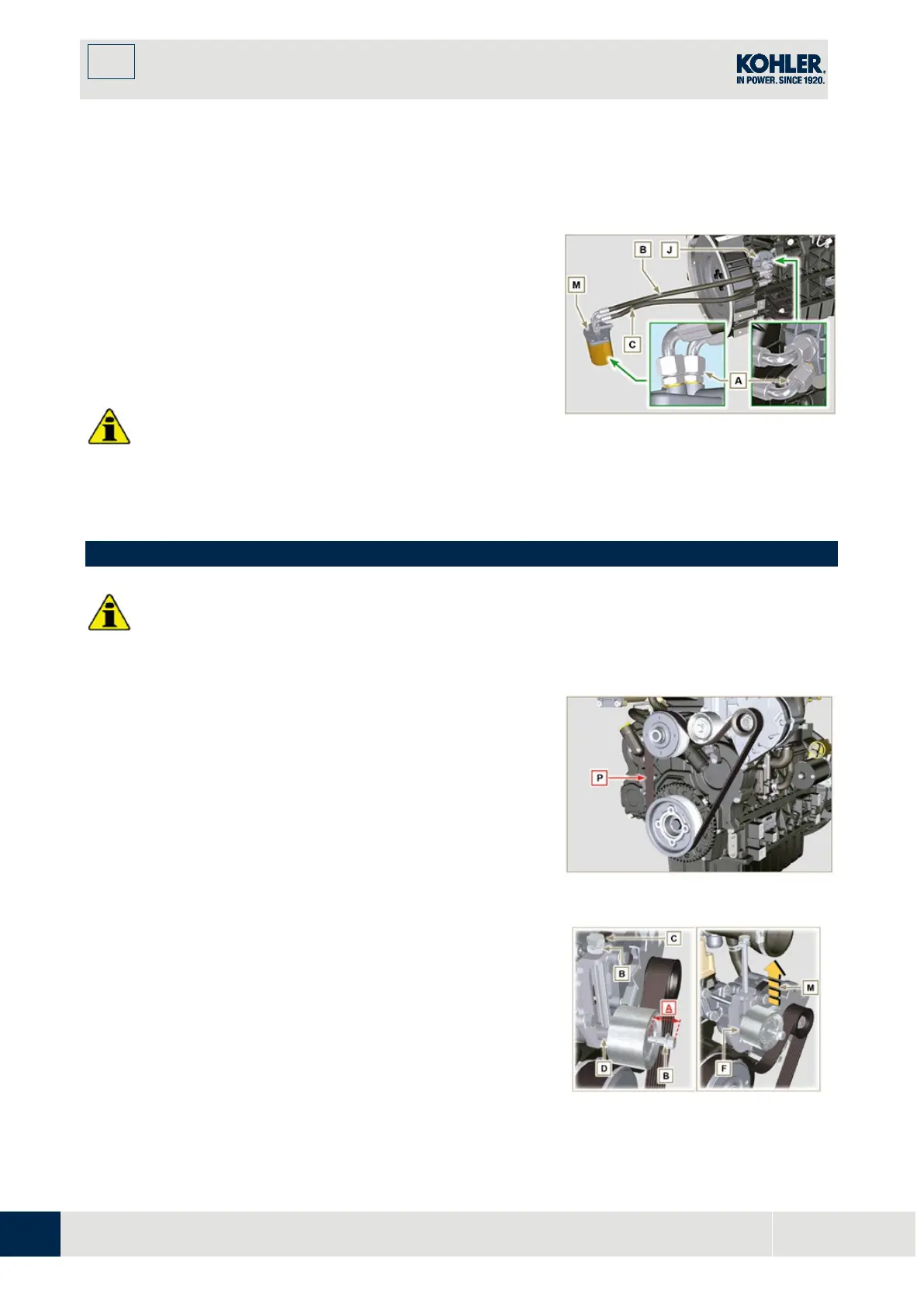
2701 on thread) as positioned in Fig. 11.39.
7.
Clamp union H on flange J inserting gasket U (tightening
torque at 40 Nm).
8.
Connect the hose B to the central fitting of support M
and of flange J.
9.
Connect the hose C to the side fitting of the support M
and of head J.
10.
Clamp the nuts A on the head J (tightening torque at 3
0
Nm).
11.
Clamp the nuts A on the support M (tightening torque a
t
35 N
m).
Imp
ortant
•
Check the tightening of the fittings K, H (Fig. 11.37) and
L (Fig. 11.38) (tightening torque at 40 Nm).
Fig 11.40
11.9 Poly-V alternator belt (replacement and adjustment)
•
Before proceeding with operation, read Par. 3.3.2.
1.
Loosen the nut B and manually tighten the screw C until
it just touches the pulley pin D.
2.
Untighten the screw E by around 32mm (A).
3.
Untighten the screw C.
NOTE: The belt tensioner pulley F should move towards the
arrow G. If it does not, please move it manually.

 Loading...


