INFORMATION ABOUT OPTIONAL
COMPONENTS
11
161
EN
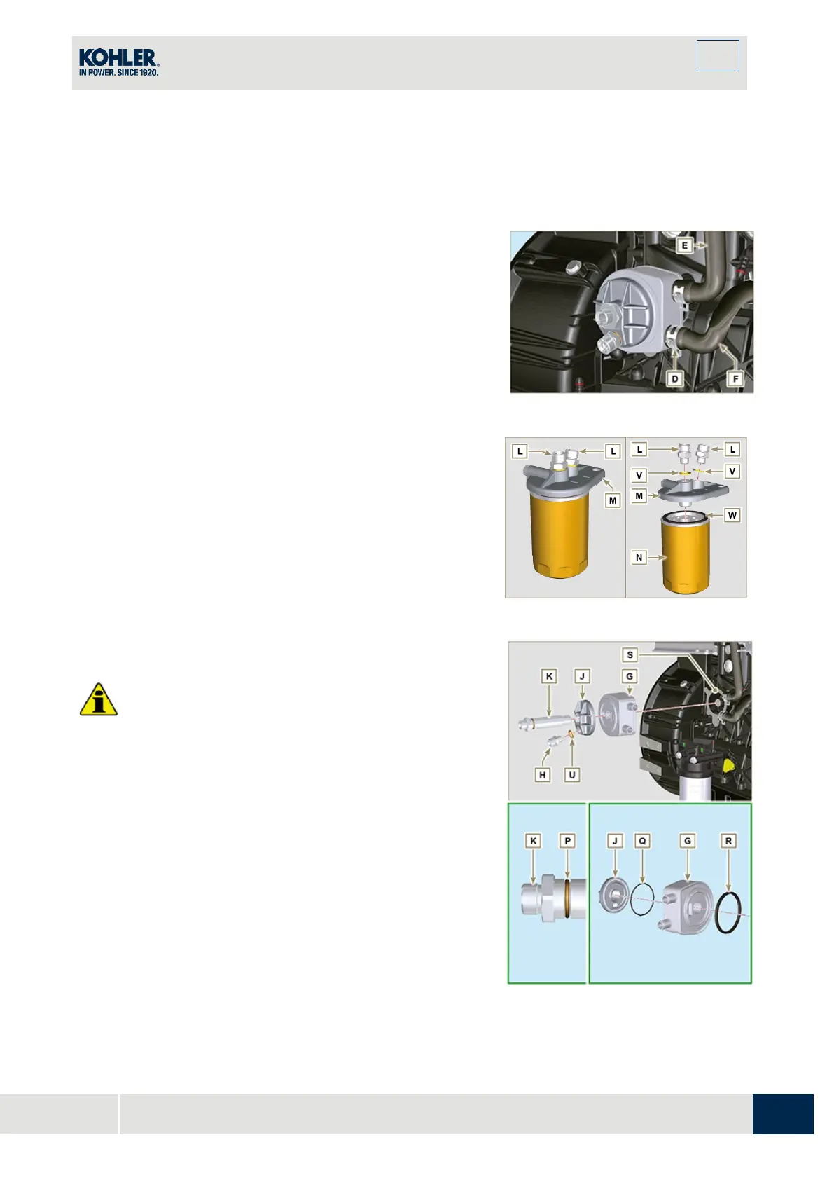
with a tool the fittings K, H (Fig. 11.37) and L
(Fig. 11.38) in order to prevent their lose
together with the nuts A, with the consequent of
oil leakage.
2.
Undo the nuts A and remove the hoses B and C.
3.
Release the clamps D and remove the hoses E and F
from Oil Cooler G.
4.
Unscrew and remove the fitting H with its copper gasket
from the oil filter head J.
5.
Unscrew and remove:
- the fitting K with the copper gasket;
- Oil Cooler G and the relative gaskets;
- the oil filter head J.
Fig 11.37
6.
Unscrew the fittings L and remove the copper gaskets
from the support M.
7.
Unscrew the cartridge N with gasket from the support M.
Fig 11.38
Important
•
Always replace the gaskets V after each assembly.
•
Always replace the gaskets P, Q, and U at each
assembly.
•
Lubricate the gaskets P, Q with oil before assembling
them.
1.
Clamp unions L on support M inserting gasket V
(tightening torque at 40 Nm).
2.
Lubricate gasket W and clamp cartridge N on support M
(tightening torque at 20 Nm).
3.
Insert the gasket P on the seat of the fitting K.
4.
Insert flange head J on the union K and the gasket Q i
n
the seat of head J.
5.
Insert the Oil Cooler G on the union K and the gasket R
in the seat of Oil Cooler G.
6.
Onto crankcase S apply Oil Cooler G and flange J by
means of union K (tightening torque at 25 Nm + Loctite
Fig 11.39

 Loading...


