ASSEMBLY INFORMATION
9
121
EN
inserting the gasket CD (tightening torque 25 Nm).
9.4 Oil sump unit assembly
9.4.1 Oil fume pipes
1.
Apply Loctite 648 on the pipe threads A.
2.
Screw and tighten the pipes A (tightening torque of
15
Nm).
Important
•
It is mandatory to replace the gasket B after each
assembly.
•
Always replace capscrews D with new ones or
alternatively apply Loctite 2701.
1.
Insert the new gasket B in the seat of the oil suctio
n
h
ose flange D.
2.
Secure the hose C on the crankcase E with the screws D
(tightening torque 10 Nm).
Fig 9.24
1.
Ensure that the contact surfaces F of the oil sump G an
d
t
he crankcase E are completely clean.
2.
Apply a bead of approx. 2.5 mm of sealant (Loctite
5660) on the surface F of the oil sump G.
3.
Position the oil sump G on the crankcase E in line with
the fastening holes (use the aid of tool
ST_18
).
NOTE: alternatively apply Loctite 5699.
Fig 9.25
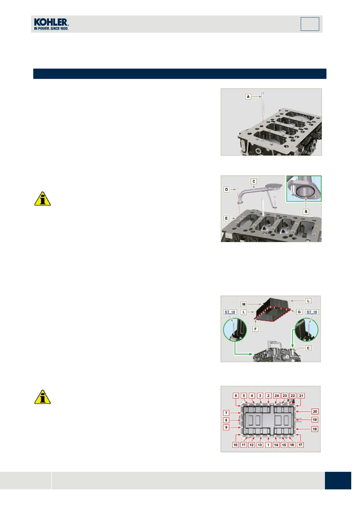
Important
•
Tighten the screws L, strictly following the sequence and
tightening torque indicated.
4.
Tighten the screws L following the sequence indicated
(tightening torque 25 Nm).

 Loading...


