9
ASSEMBLY INFORMATION
EN 120
•
Failure to adhere to the assembly procedures may
compromise the functionality of the engine, and also
cause damage to persons and property.
13.
Tighten the screws
AU
, alternately, strictly following the
tightening torques indicated.
Tightening sequence of screws Torx M10x1:
1° CYCLE
- with a torque of
40
Nm
;
2°
CYCLE
- with a torque of
85
Nm
;
14.
Check that the connecting rods have axial play and th
e
cr
ankshaft W rotates smoothly.
NOTE
: After the check carried out at point 14, position the shaft
W
with the first cylinder to TDC.
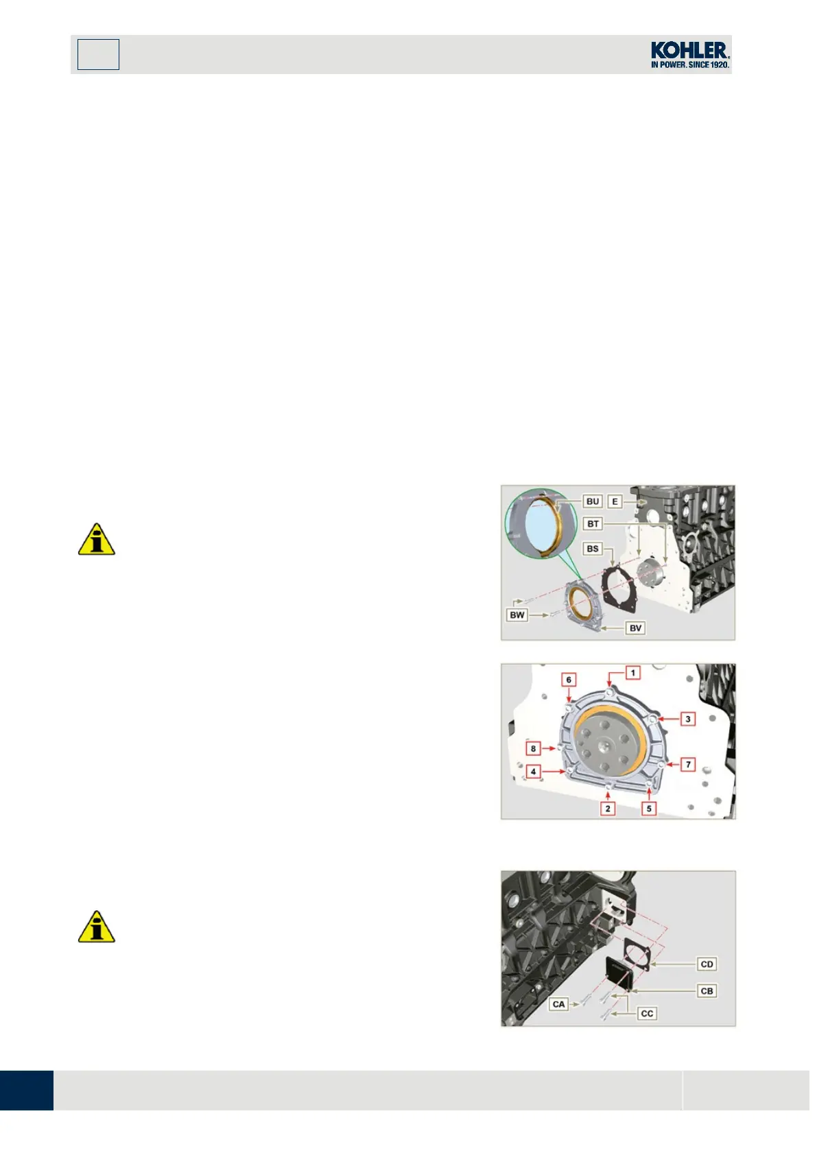
9.3.10 Crankshaft gasket flange
Important
•
Check that the contact surface between the flange and
the crankcase is free of grit and dirt.
•
Always replace the gasket BS after each assembly.
1.
Check that there are bushings BT on the crankcase E.
2.
Lubricate the oil seal lip BU.
3.
Position the gasket BS and flange BV on the crankcase
E i
n correspondence with the bushings BT.
4.
Put Loctite 243 on the 2 screws BW matching the
bushings BT.
5.
Screw the fastening screws all the way in BW without
tightening them.
6.
Tighten all the screws BW strictly following the
tightening sequence indicated (tightening torque to
10
Nm).
F
ig 9.21 a
Fig 9.21 b
9.3.11 Cover 3
PTO
Important
•
Replace capscrews CA with each assembly or
alternatively apply Loctite 2701 on the thread.
1.
Secure the cover CB with the screws CA and CC

 Loading...


