8
INFORMATION ABOUT OVERHAULING
EN 110
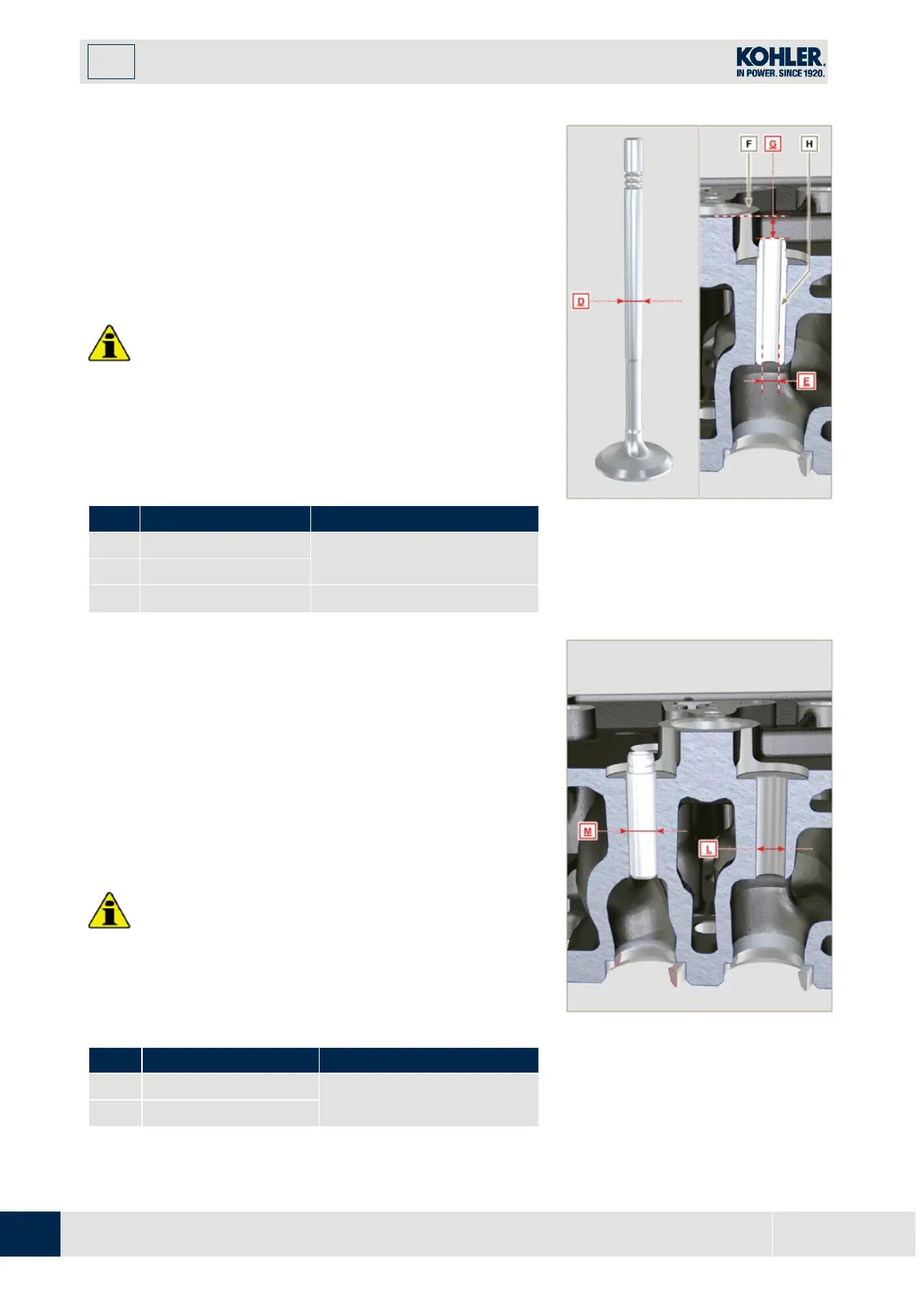
M
easure the diameters
D
and
E
of the rods and guides valve
(Tab. 8.10)
.
If the diameters don't correspond to the values indicated,
replace the valves or guides.
The
MAX
allowed value of wear for
D and E
is 0.10 mm.
Observe values G from surface F when assembling guides H
(Tab. 8.10).
Important
•
Carry out the measurements in different points to detec
t
an
y ovalisation and/or concentrated wear.
•
Tab. 8.10 details the dimensional values of new
components only.
•
Tab 8.10 Valve stem - valve guide dimensions
0.040 - 0.064
Fig 8.23
8.6.5 Valve guides replacement
The intake and exhaust guides are both made out of grey iron
with pearlitic phosphoric matrix and they have the same
dimensions.
The guides are press-fit assembled; assembly is possible by
cooling the guides with the aid of liquid nitrogen.
Before assembling a new guide, measure value L and
M,calculate the press-fit value, which must observe the values in
Tab. 8.11.
Observe values G from surface F when assembling guides H
(Tab. 8.10 - Fig. 8.23).
Important
•
The guides must be worked for value E (Tab. 8.10 -
Fig.8.23) after driving. Contact a rectification workshop
for such operations.
Tab 8.11 valve guides - housing dimensions
0.030 - 0.054
Fig 8.24

 Loading...


