TECHNICAL INFORMATION
2
41
EN
2.15.8 Fuse
D
evice
G
is assembled on cylinder head
P
(flywheel side); it
protects the electrical circuit in the event of an overload or
short circuit.
N
OTE:
Component not necessarily supplied by
KOHLER.
Fig 2.41
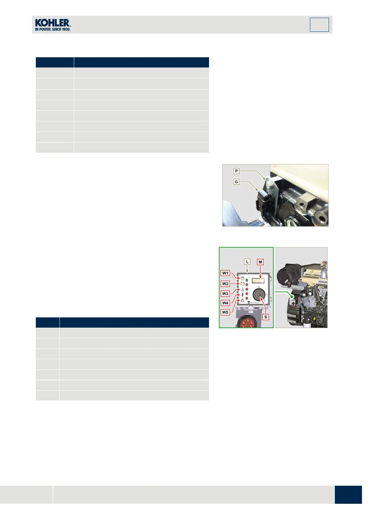
2.15.9 Control panel (optional)
Panel L can be assembled on the engine or machine.
The connectors are described in Tab. 2.36, the main functions
are illustrated.
N
OTE:
Component not necessarily supplied by
KOHLER.
Tab 2.36
Control switch to start the engine
Warning Light - battery not charging
Warning Light - engine oil not pressurised
Warning Light - high coolant temperature
Warning Light - alarm general indicator
Fig 2.42

 Loading...


