INFORMATION FOR REPLACING THE
FUNCTIONAL UNITS
6
73
EN
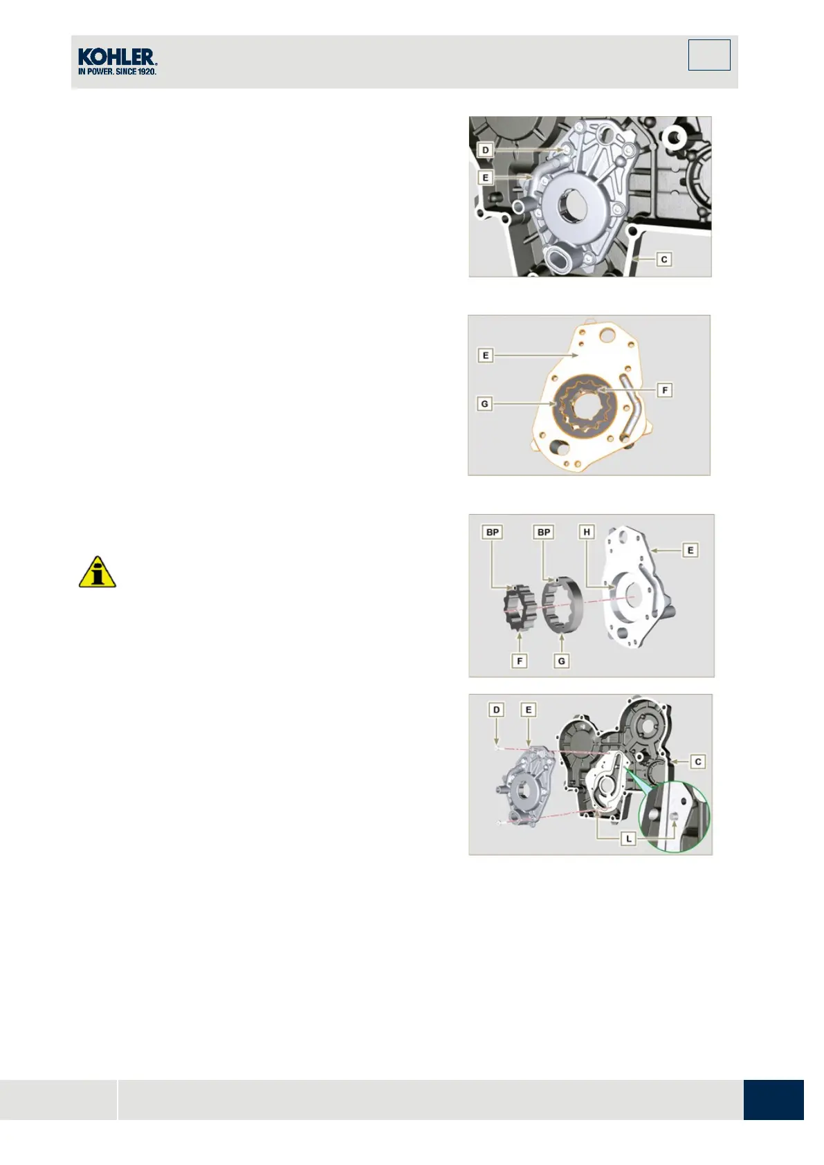
6.4.4 Oil pump disassembly
1.
Undo the screws D and remove the group pump E
from the timing system crankcase C.
2.
Remove the rotors F and G from the oil pump
crankcase E.
Fig 6.39
Fig 6.40
Important
•
Carry out the checks described in Par. 8.7 prior t
o
a
ssembly.
1.
Check that all surfaces in contact between F, G, H
,
E
and C are free from impurities - scratches -
dents.
2.
When assembling, do not use any type of gasket
between E and C.
3.
Thoroughly lubricate the seat of the rotors H on the
oil pump crankcase E and the two rotors F and G.
4.
Within housing H insert the 2 rotors (in sequence)
G
an
d F, observing the references BP as described in
figure (or refer to Par. 2.10.2).
5.
Check that the 2 pins L are inserted properly in th
e
t
iming system crankcase C.
6.
Position the oil pump carter E using the referen
ce
pins L.
7.
Clamp the oil pump carter E with the screws D
(tightening torque 10 Nm - ST_06).
Fig 6.41
F
ig 6.42

 Loading...


