Appendix page 109
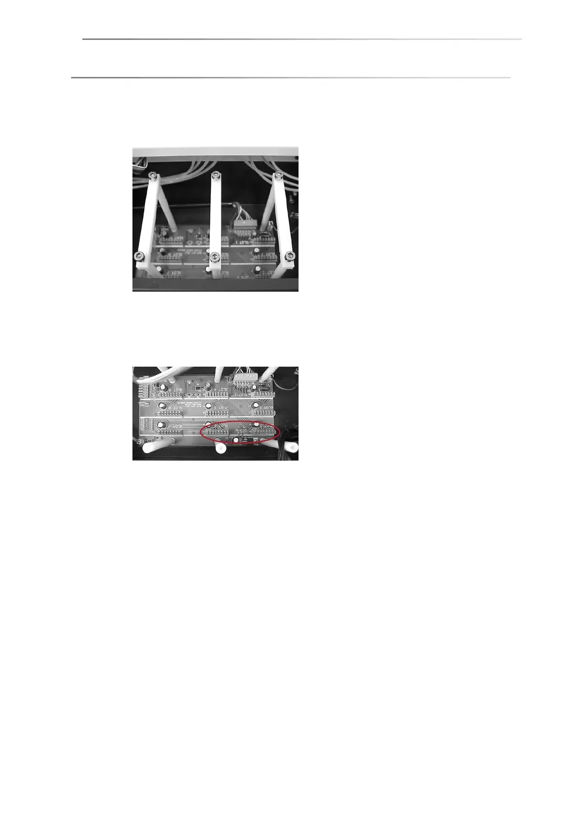
4. The Bus board for plugging in the EM3201 board is located underneath the
cover, more precisely underneath the three white plastic frames (board
support):
Loosen one screw on each of the frames and turn them aside.
5. From the rear view of the instrument the connections of the Bus board are
labelled upside down. Plug the electronics board in two of the slots. The slots
and components must point to the rear.
Take care that the whole width of the socket is used for the board so that all
poles are occupied. If the board is not properly connected it can be
destroyed when switching on the DSA100.
Depending on the current equipment, ports can already be occupied.