2PV/2PW-2
1-5-75
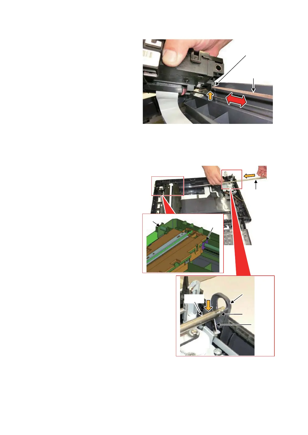
59. Fit the ISU drive belt to the groove at
the ISU bottom side.
Confirm the teeth of the ISU drive belt
face the machine front side before fit-
ting as above.
After fitting, confirm the ISU drive belt
and the ISU are connected by horizon-
tally shifting the ISU (in the red arrow's
direction in the figure).
Figure 1-5-121
60. Pass the shaft removed at Step 54
through the holes (K, L) of the scanner
frame's machine left side and the ISU's
machine rear side, and then fit the
groove of the shaft to the locking hole of
the scanner frame's machine right side.
*: After that, confirm the edge of the ground
spring is fitted to the groove (F) of the
shaft.
Figure 1-5-122
ISU drive belt
Groove fo locking
the ISU drive belt
K
L
Shaft
Locking hole
Groove F
of the shaft
Ground
spring
Shaft
 Loading...