130
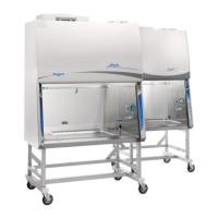
4. Pull each LED Lamp straight toward you to release the lamp from the two Spring
Clips holding it in place (Figure 12-43). Note the rotational position of the old LED
lamps (there is a dead band stripe that will need to be oriented the same when
reinstalling the new LED Lamps).
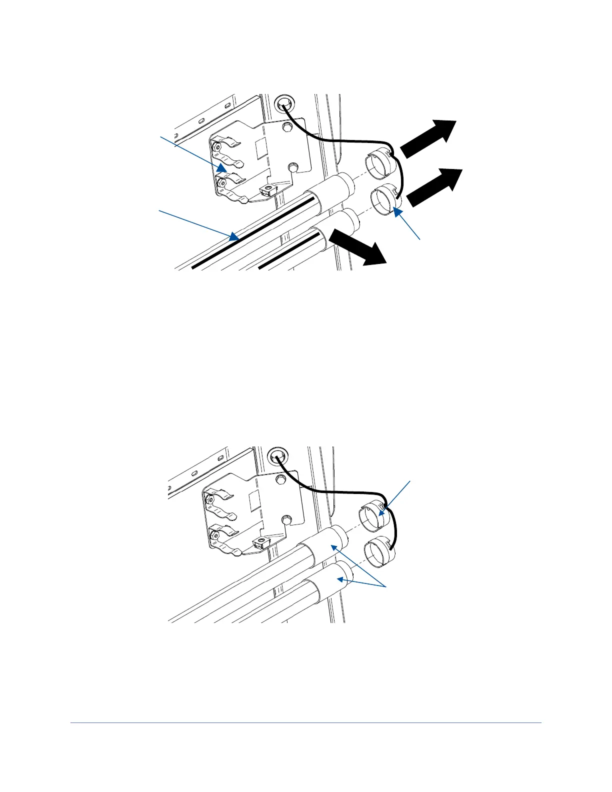
5. Install the new LED Lamps by reversing the removal procedure. Take care to look
at both ends of the new LED Lamps. One end is labeled with a ‘+’ & ‘-‘ and ‘L’ & ‘N’
(Figure 12-44). This end of the new LED Lamp must go to the right, and is inserted
into the Socket Cap.
6. When reinstalling the Left End Cap, the pins on each LED Lamp must align
rotationally with the Left End Cap. This ensures the dead band stripe is positioned
correctly for maximum cabinet lighting.