147
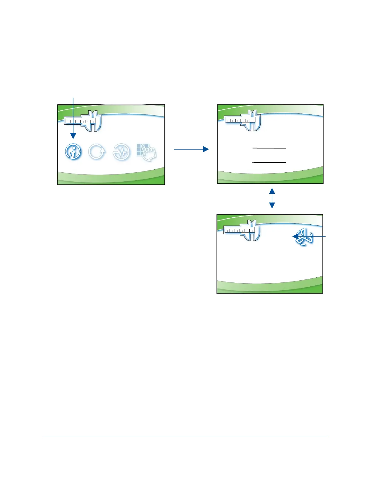
2. To verify the PWM measured in step 1 c (above) is correct, access the Tools
submenu from the display. Follow the steps in Figure 13-8 to identify the PWM
signal the microprocessor is sending to the blower motor.
3. Divide the PWM voltage measured in step 1 c (above) by the DC voltage
measured in step 1 b (above). For example, 13.7 volts measured across pins 1
& 10 (PWM line), and 23.7 volts measured across pins 1 & 15. [13.7] / [23.7] =
0.58. This means the PWM signal is 0.58 = 58%. The Blower PWM value
displayed under the Info screen (above) should match this calculated value.