172
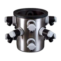
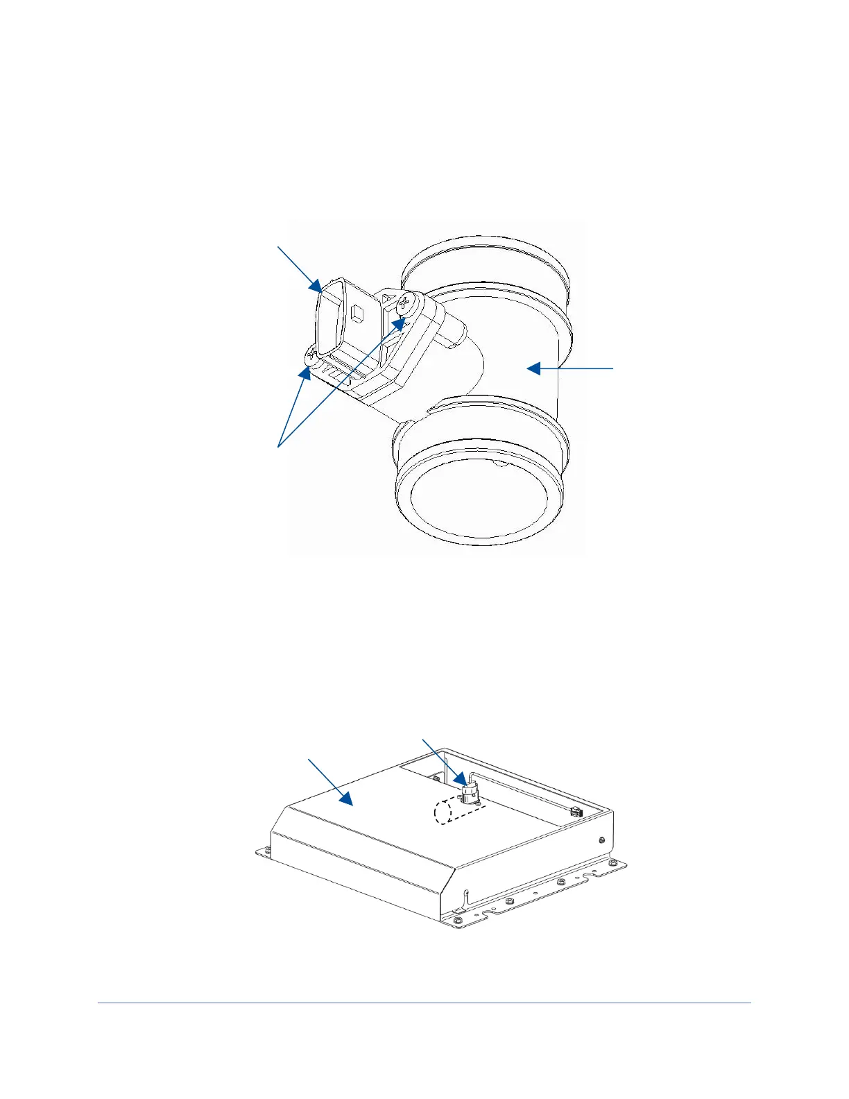
4. On the new airflow sensor, remove the two screws holding the sensor into its
body. See Figure 18-2. Do NOT pull the sensor out of the body.
5. Position the sensor on the underneath side of the exhaust cover so that the
screen end of the sensor body is oriented towards the front of the biosafety
cabinet. Reinstall the two screws removed in the previous step through the
exhaust cover and into the sensor body. Tighten the two screws. See Figure 18-
3 for reference.