80
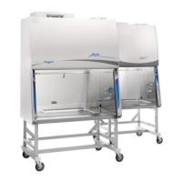
3. Insert the appropriate left and right stop into the recess in each corner post, as
shown in Figure 10-31. Lower the sash until it contacts the Sash Stops.
4. Locate the single row of holes at the front-most edge of the grille, see Figure 10-
31.
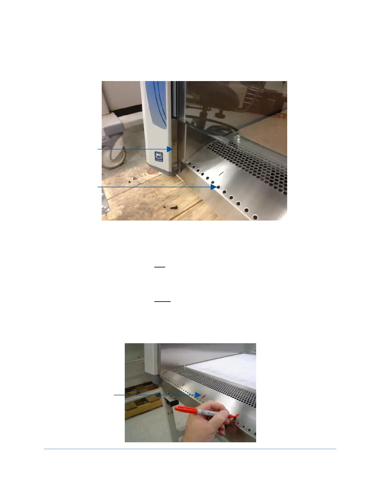
5. Mark the 6
th
hole from the left side wall and subsequently mark every 9
th
hole
until the number of test points marked equals the width of the biosafety cabinet in
feet. For example, a 5-ft width model should have 5 test points marked.
6. Mark the 6
th
hole from the right side wall and subsequently mark every 9
th
hole
until the number of test points marked equals the width of the biosafety cabinet in
feet. For example, a 5-ft width model should have 5 test points marked. All test
points should be marked on the grille. See Figure 10-32 for reference.