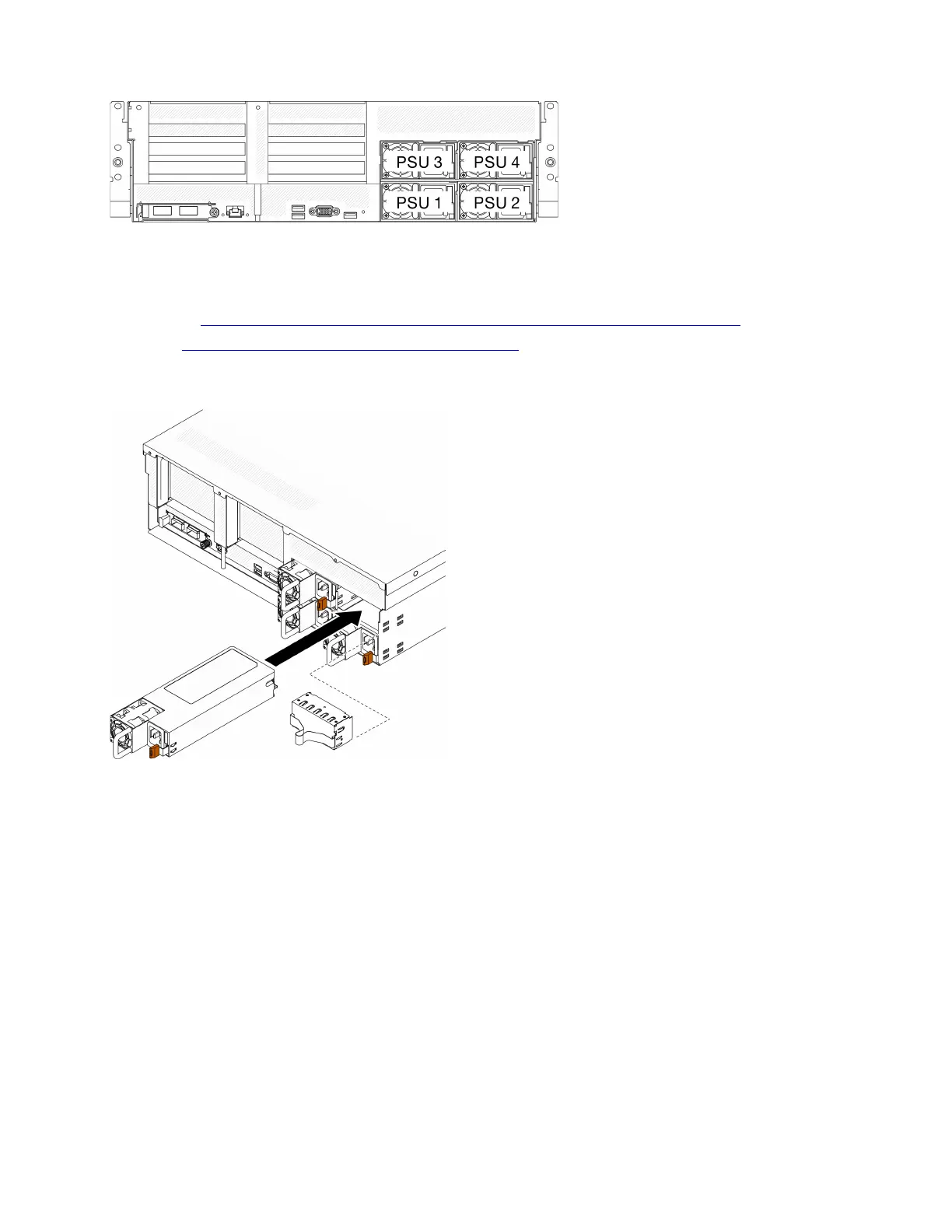
Figure 139. Power supply bay numbering
Watch the procedure. A video of the installation and removal process is available:
• YouTube:
https://www.youtube.com/playlist?list=PLYV5R7hVcs-BXei6L6c05osQVLt4w5XYx
• Youku: https://list.youku.com/albumlist/show/id_59636529
Procedure
Figure 140. Installing power supply unit
Step 1. If a power supply filler is installed in the bay, pull the filler out of the bay.
Step 2. Align the power supply unit with the bay; then, slide the power supply unit into the bay until the
release tab locks into place.
Step 3. Connect the power supply unit to a properly grounded electrical socket with a power cord.
Step 4. Make sure that the ac power LED on the power supply unit is lit, indicating that the power supply
unit is operating correctly.
Important: During normal operation, each power supply bay must contain either a power supply
unit or a power supply filler for proper cooling.
After you finish
Check the PSU LEDs to verify that the PSU is operating correctly. See Figure 9 “Power supply LEDs” on
page 23.
Chapter 4. Hardware replacement procedures 199

 Loading...


