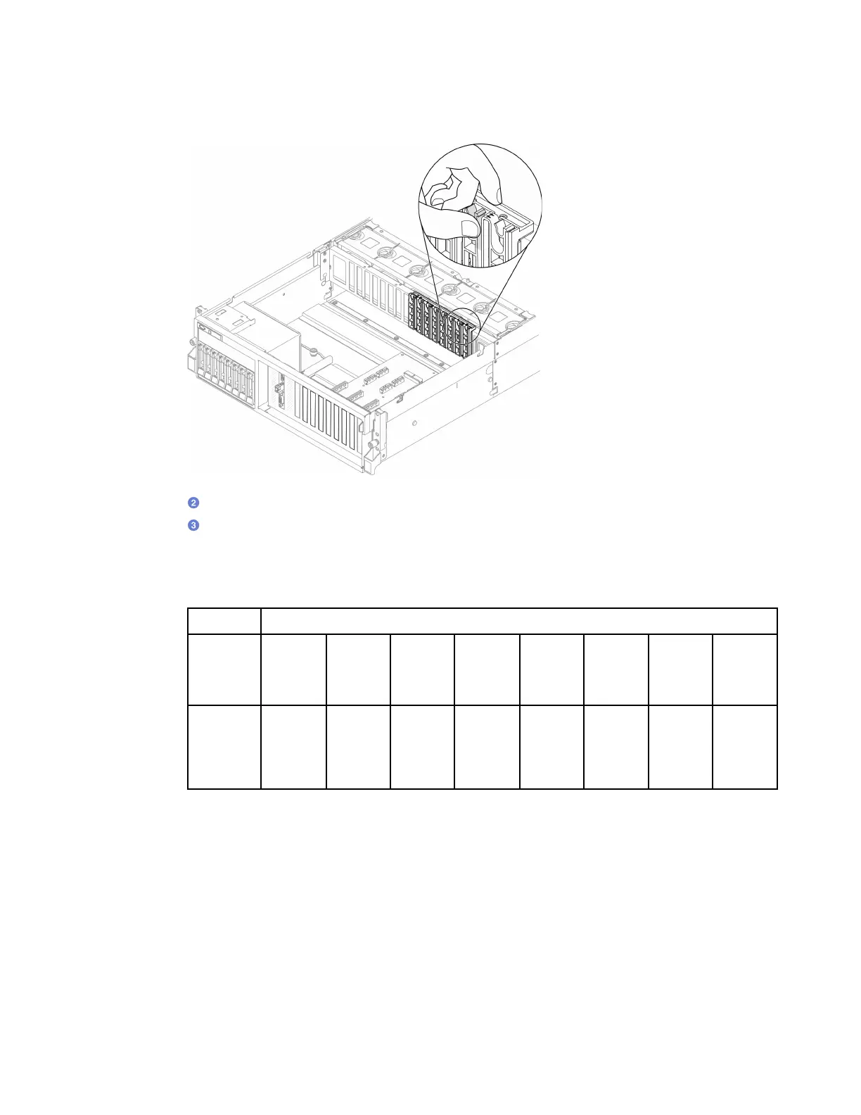
Note: Make sure that the rear end of each adapter is inserted into the slot next to the two
imprinted arrows on the chassis.
b. Fasten the GPU adapter retention screw.
c.
Connect the GPU adapter power cable to the GPU adapter. Refer to the GPU adapter and
system board GPU power connector mapping table. For more details on GPU power
connectors on system board, see “System-board connectors” on page 34.
Table 22. GPU adapter and system board GPU power connector mapping table
Item Numbering
GPU
adapter
(PCIe slot)
1
(Slot 3)
2
(Slot 4)
3
(Slot 5)
4
(Slot 6)
5
(Slot 7)
6
(Slot 8)
7
(Slot 9)
8
(Slot 10)
System
board
GPU
power
connector
1 2 3 4 5 6 7 8
After you finish
• To install the GPU adapter link bridge, see “Install a GPU adapter link bridge” on page 262.
• Complete the parts replacement. See “Complete the parts replacement” on page 328.
GPU distribution board replacement
Follow instructions in this section to remove and install a GPU distribution board.
Remove a GPU distribution board
Follow instructions in this section to remove a GPU distribution board.
Chapter 4. Hardware replacement procedures 255

 Loading...


