The SXM GPU Model front view
This section contains information about the controls, LEDs, and connectors on the front of the SXM GPU
Model server.
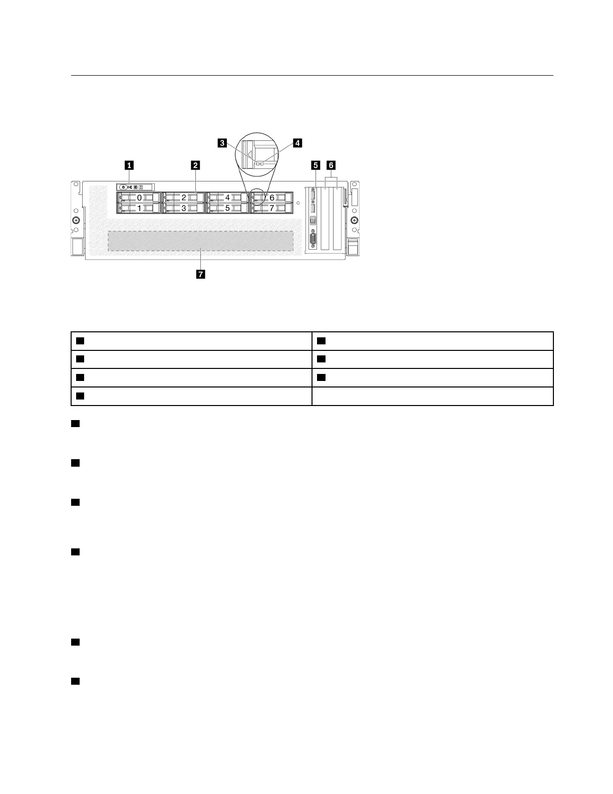
Figure 7. Front view of the SXM GPU Model
Table 8. Components on the front view of the SXM GPU Model
1 Front panel
5 Front I/O module
2 2.5-inch drive bays (bay 0 to 7) 6 PCIe slots 1-2
3 Drive activity LED (green) 7 GPU-L2A assembly
4 Drive status LED (yellow)
1 Front panel
For more information about the front panel, see “Front panel” on page 25.
2 2.5-inch drive bays (bay 0 to 7)
Install 2.5-inch drives to these bays. See “Install a 2.5-inch hot-swap drive” on page 265.
3 Drive activity LED (green)
Each hot-swap drive comes with an activity LED. When this LED is flashing, it indicates that the drive is in
use.
4 Drive status LED (yellow)
The drive status LED indicates the following status:
• The LED is lit: the drive has failed.
• The LED is flashing slowly (once per second): the drive is being rebuilt.
• The LED is flashing rapidly (three times per second): the drive is being identified.
5 Front I/O module
For more information about the front I/O module, see “Front I/O module” on page 26.
6 PCIe slots 1-2
Install PCIe adapters, particularly network adapters to these slots. These PCIe slots support the following
configuration:
Chapter 2. Server components 21

 Loading...


