Table 13. System-board connectors (continued)
16 Fan 2 connector 37 Processor 2 UPI connector
17 Fan 1 connector
38 PCIe connector 16 (rear PCIe riser 2)
18 PCIe connector 6, 5, 4, 3, 2, 1 (left to right)
39 Processor 1 UPI connector
19 Front I/O expansion board power connector 40 Rear PCIe riser power 2 connector
20 PCIe adapter distribution board power 1 connector
41 Intrusion switch connector
21 GPU power connector 4, 3, 2, 1 (left to right) 42 Serial port cable connector
Note:
1
Front I/O module cables connect to these connectors.
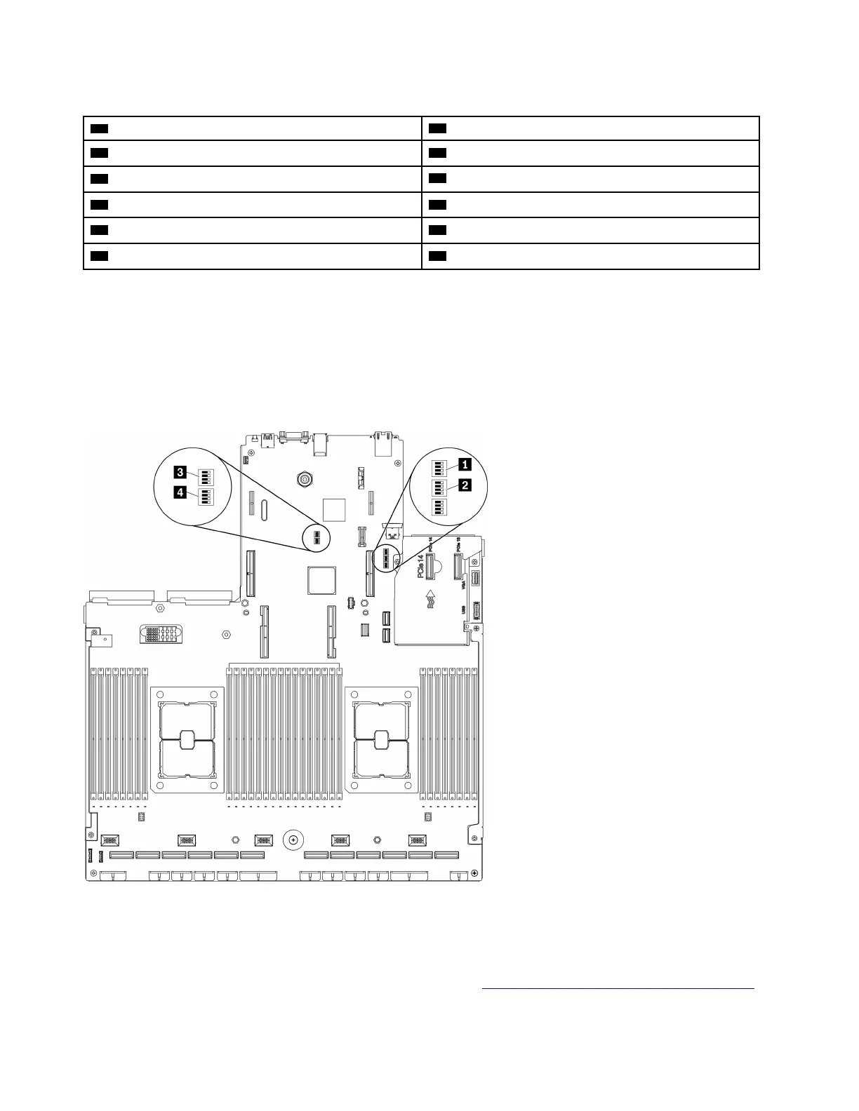
System-board switches
The following illustrations show the location of the switches, jumpers, and buttons on the server.
Note: If there is a clear protective sticker on the top of the switch blocks, you must remove and discard it to
access the switches.
Figure 14. System-board switches
Important:
1. Before you change any switch settings or move any jumpers, turn off the server; then, disconnect all
power cords and external cables. Review the information in
http://thinksystem.lenovofiles.com/help/topic/
36 ThinkSystem SR670 V2 Maintenance Manual

 Loading...


