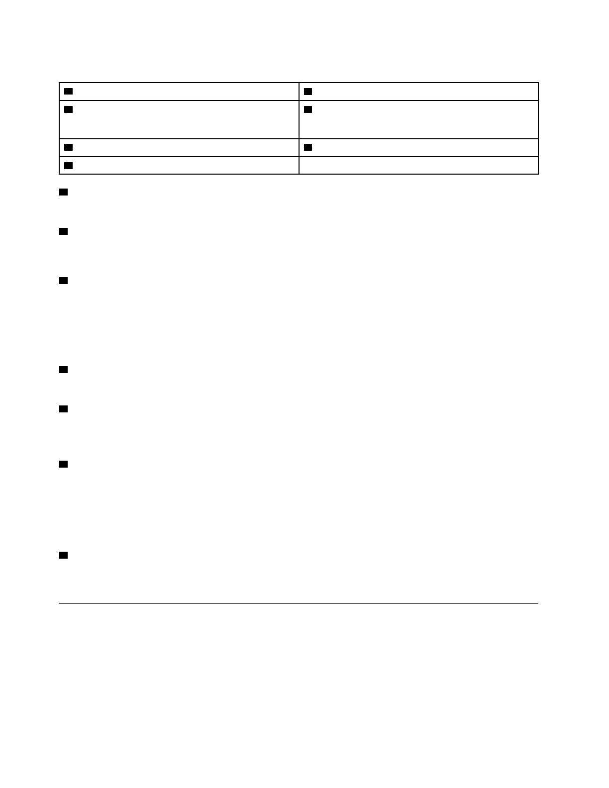
Table 6. Components on the front view of 3.5-inch drive configuration
1 Front panel
5 PCIe slot 3-6
2 Drive activity LED (green) 6 PCIe slots 1-2
Not available when rear PCIe riser 1 and rear PCIe riser 2
are installed.
3 Drive status LED (yellow) 7 3.5-inch drive bays (bay 0 to 3)
4 Front I/O module
1 Front panel
For more information about the front panel, see “Front panel” on page 25.
2 Drive activity LED (green)
Each hot-swap drive comes with an activity LED. When this LED is flashing, it indicates that the drive is in
use.
3 Drive status LED (yellow)
The drive status LED indicates the following status:
• The LED is lit: the drive has failed.
• The LED is flashing slowly (once per second): the drive is being rebuilt.
• The LED is flashing rapidly (three times per second): the drive is being identified.
4 Front I/O module
For more information about the front I/O module, see “Front I/O module” on page 26.
5 PCIe slot 3-6
Install PCIe adapters, particularly GPUs to these slots. These PCIe slots support the following configuration:
• PCIe slot 3-6, PCIe x16, double-wide, FH/FL
6 PCIe slots 1-2
Not available when rear PCIe riser 1 and rear PCIe riser 2 are installed.
Install PCIe adapters, particularly network adapters to these slots. These PCIe slots support the following
configuration:
• PCIe slot 1-2, PCIe x16, FH/FL
7 3.5-inch drive bays (bay 0 to 3)
Install 3.5-inch drives to these bays. See “Install a 2.5-/3.5-inch hot-swap drive” on page 230 for more
information.
The 8-DW GPU Model Front view
This section contains information about the controls, LEDs, and connectors on the front of the 8-DW GPU
Model server.
18
ThinkSystem SR670 V2 Maintenance Manual

 Loading...


