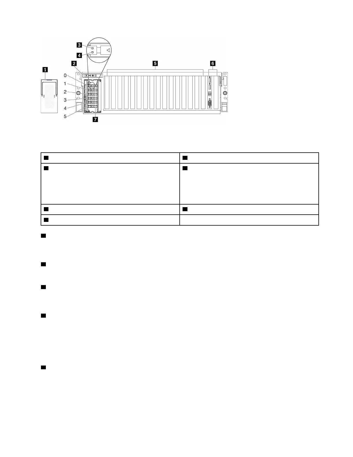
Figure 6. Front view of the 8-DW GPU Model
Table 7. Components on the front view of the 8-DW GPU Model
1 EDSFF drive cage cover 5 PCIe slot 3-10
2 Front panel
6 Front I/O module or PCIe Slot 1-2
One of the following is supported:
• Front I/O module
• PCIe Slot 1 and slot 2 (Not available when rear PCIe
riser 1 and rear PCIe riser 2 are installed.)
3 Drive activity LED (green) 7 ESDFF drive bays (bay 0 to 5)
4 Drive status LED (yellow)
1 EDSFF drive cage cover
The 8-DW GPU Model servers should always operate with the EDSFF drive cage cover installed to the
chassis.
2 Front panel
For more information about the front panel, see “Front panel” on page 25.
3 Drive activity LED (green)
Each hot-swap drive comes with an activity LED. When this LED is flashing, it indicates that the drive is in
use.
4 Drive status LED (yellow)
The drive status LED indicates the following status:
• The LED is lit: the drive has failed.
• The LED is flashing slowly (once per second): the drive is being rebuilt.
• The LED is flashing rapidly (three times per second): the drive is being identified.
5 PCIe slot 3-10
Install PCIe adapters, particularly GPUs to these slots. These PCIe slots support one of the following
configurations:
• PCIe slot 3-10, PCIe x16, double-wide, FH/FL
• PCIe slot 3-10, PCIe x16, single-wide, FH/FL
Chapter 2. Server components 19

 Loading...


