4-DW GPU Model with 8x 2.5-inch drives cable routing
Follow the instructions in this section to learn how to do cable routing for 4-DW GPU Model with 8x 2.5-inch
drives.
Identifying connectors
Go through the following sections to acquire necessary information before starting cable routing.
• For the connectors on system board, see “System-board connectors” on page 34.
• For the connectors on the drive backplane, GPU distribution board, rear riser, and front I/O expansion
board, see “Identifying connectors” on page 58.
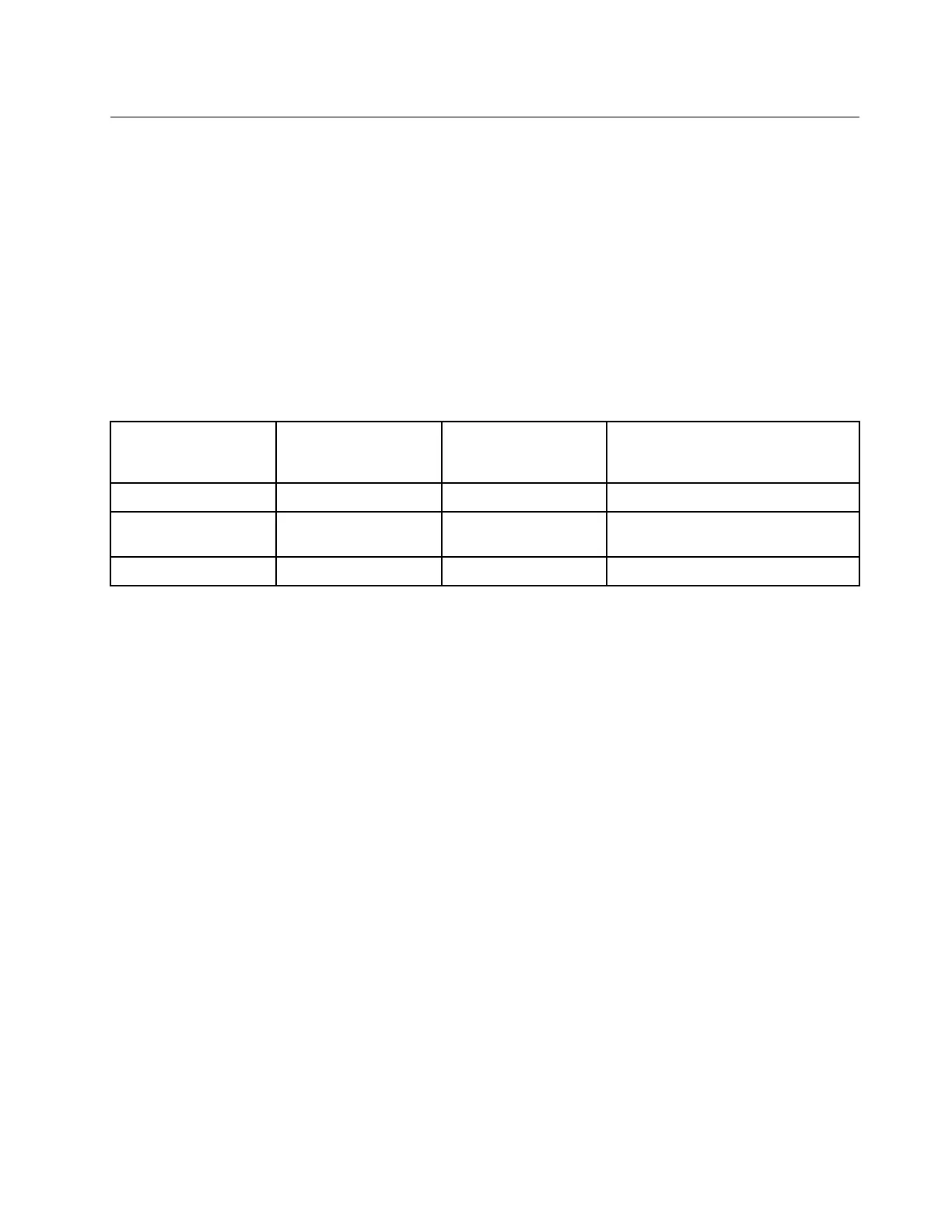
4-DW GPU Model with 8x 2.5-inch drives configurations
Cable routing is different by configuration. See the table below for the configuration that matches your
server, and refer to the corresponding cable routing guide.
Rear riser 1
Rear riser 2 installed
with HBA/RAID
adatper
Front I/O expansion
board
Configurations
V
Configuration A
V V
Configuration A with HBA/RAID
adapter
V
Configuration C
Refer to the corresponding cable routing guide:
• For Configuration A, see “Configuration A cable routing” on page 67
• For Configuration A with HBA/RAID adapter, see “Configuration A with HBA/RAID adapter cable routing”
on page 72
• For Configuration C, see “Configuration C cable routing” on page 77
Chapter 3. Internal cable routing 65

 Loading...


