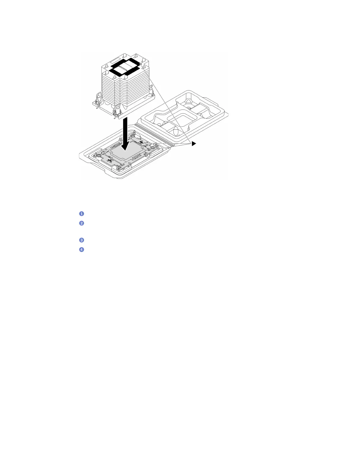
c. Press the carrier into place until the clips at all four corners engage.
Figure 150. Assembling the PHM with processor in shipping tray
Step 6. Install the processor-heat-sink module into the system board socket.
a.
Rotate the anti-tilt wire bails inward.
b.
Align the triangular mark and four Torx T30 nuts on the PHM with the triangular mark and
threaded posts of the processor socket; then, insert the PHM into the processor socket.
c.
Rotate the anti-tilt wire bails outward until they engage with the hooks in the socket.
d.
Fully tighten the Torx T30 nuts in the installation sequence shown on the heat-sink label.
Tighten the screws until they stop; then, visually inspect to make sure that there is no gap
between the screw shoulder beneath the heat sink and the processor socket
Note: For reference, the torque required for the fasteners to fully tighten is 1.1 newton-meters, 10
inch-pounds.
Attention: To prevent damage to components, make sure that you follow the indicated installation
sequence.
Chapter 4. Hardware replacement procedures 211

 Loading...


