Mechanical installation
Standard devices in the power range 0.37 ... 11 kW
Thermally separated mounting (push−through technique)
4
145
EDKVF9333V DE/EN/FR 7.2
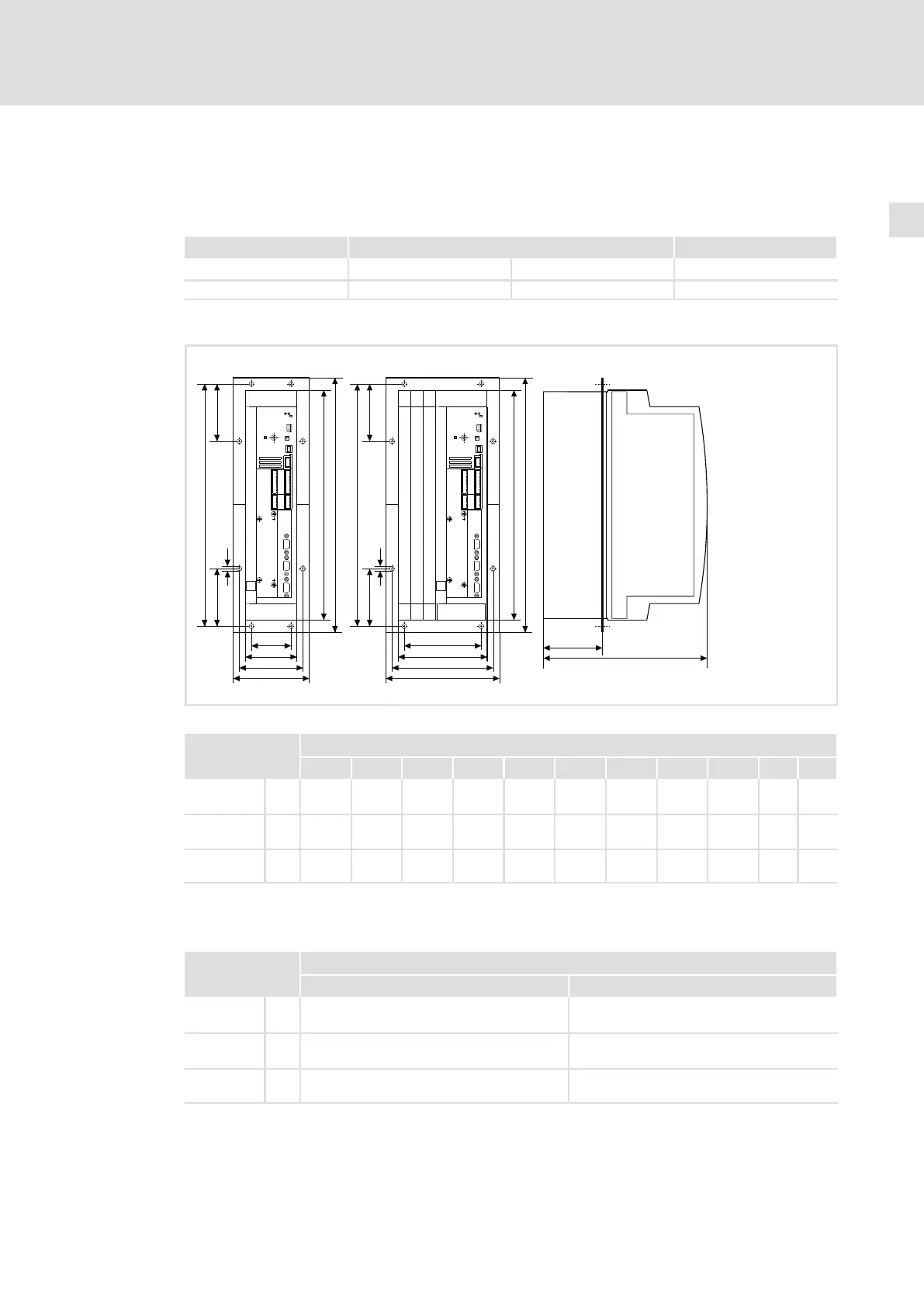
4.1.3 Thermally separated mounting (push−through technique)
For mounting in push−through technique, the drive controller of type EVF93xx−EV must be
used. In addition, the mounting set for push−through technique is required.
Type Mounting set Type Mounting set
EVF9321−EV, EVF9322−EV EJ0036
EVF9323−EV, EVF9324−EV EJ0037 EVF9325−EV, EVF9326−EV EJ0038
Dimensions
a1a1
c1c1
aa
cc
gg
d1d1
d1d1
dd
b1b1
bb
LL
10
e
f
9300vec115
Fig. 4−2 Dimensions for thermally separated mounting 0.37 ... 11 kW
9300 vector Dimensions [mm]
Type a a1 b b1 c c1 d d1 e
1)
f g
EVF9321−EV
EVF9322−EV
112.5 78 385.5 350 60 95.5 365.5 105.5 250 92 6.5
EVF9323−EV
EVF9324−EV
131.5 97 385.5 350 79 114.5 365.5 105.5 250 92 6.5
EVF9325−EV
EVF9326−EV
169.5 135 385.5 350 117 152.5 365.5 105.5 250 92 6.5
1)
For a fieldbus module plugged onto X1, consider mounting space for connecting cables
Mounting cutout in control cabinet
9300 vector Dimensions [mm]
Type Width Height
EVF9321−EV
EVF9322−EV
82 350
EVF9323−EV
EVF9324−EV
101 350
EVF9325−EV
EVF9326−EV
139 350

 Loading...


