Electrical installation
Standard devices in the power range 15 ... 30 kW
Motor connection
5
183
EDKVF9333V DE/EN/FR 7.2
5.5.5 Motor connection
Note!
ƒ Fusing the motor cable is not required.
ƒ The drive controller features 2 connections for motor temperature
monitoring:
– Terminals T1, T2 for connecting a PTC thermistor or thermal contact
(NC contact).
– Pins X8/5 and X8/8 of the incremental encoder input (X8) for connecting a
KTY thermal sensor.
Shield sheet installation
Stop!
Do not use lugs as strain relief.
PE
T1
T2
U
VW
a
3.4Nm
30 lb-in
a
0
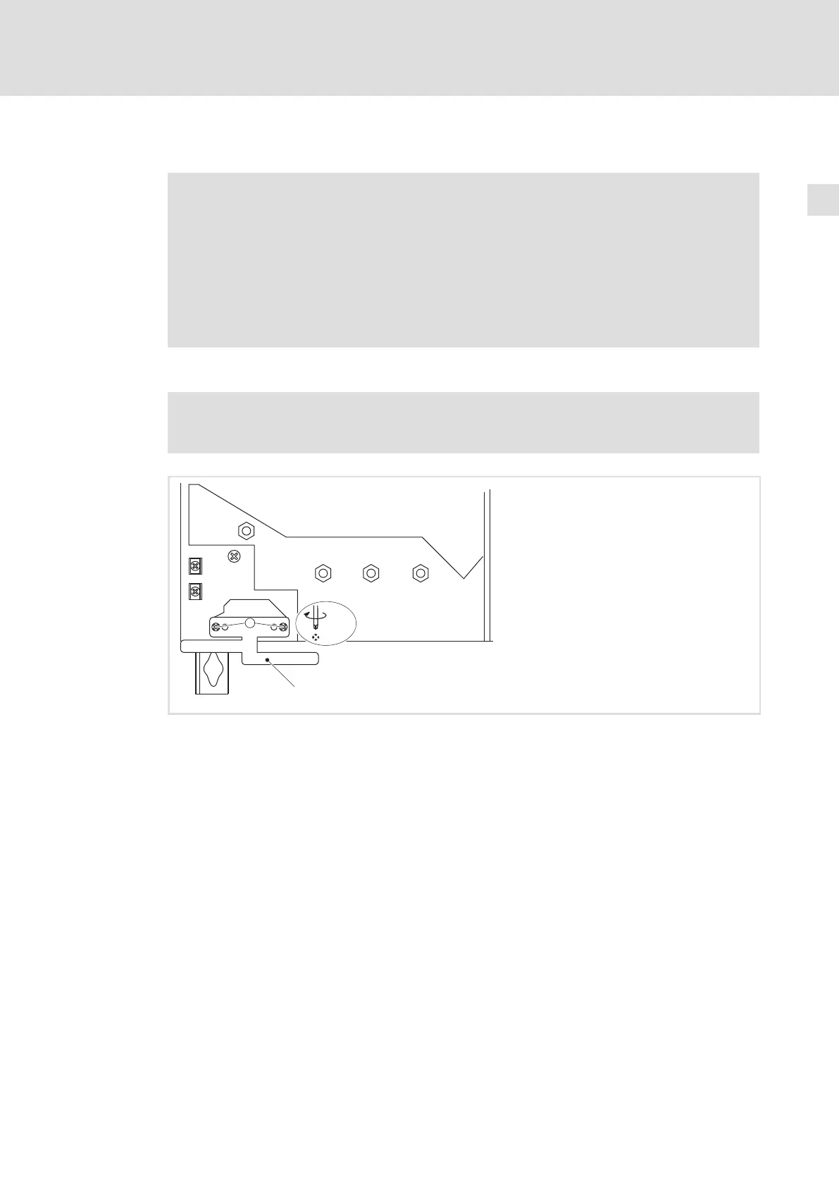
9300vec131
Fig. 5−10 Installation of shield sheet for drive controllers 15 ... 30 kW
Fasten the shield sheet with two self−tapping screws Æ 4 × 14 mm (a)
 Loading...


