Mechanical installation
Standard devices with a power of 45 kW
Mounting with fixing brackets (standard)
4
154
EDKVF9333V DE/EN/FR 7.2
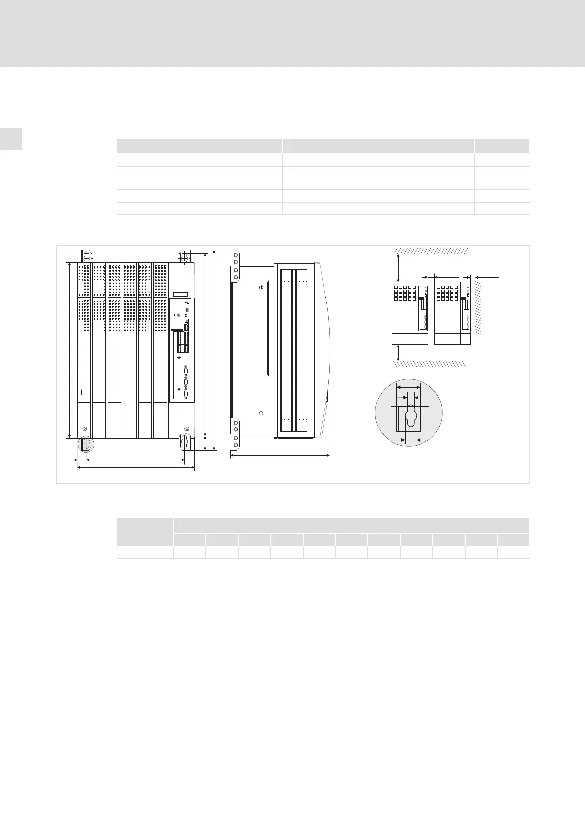
4.3.2 Mounting with fixing brackets (standard)
Mounting material required from the scope of supply:
Description Use Quantity
Fixing bracket Drive controller fixing 4
Hexagon head cap screw M8 × 16 mm
(DIN 933)
Mounting of fixing bracket to the drive controller 4
Washer Æ 8.4 mm (DIN 125) For hexagon head cap screw 4
Spring washer Æ 8 mm (DIN 127) For hexagon head cap screw 4
Dimensions
a
c1
e
b1
d
d1
b
l
c
³ 50mm
³ 50mm
g
m
k
0
³ 100mm
³ 100mm
9300vec133
Fig. 4−7 Standard mounting with fixing brackets 45 kW
Arrange drive controllers in a row with spacing to be able to remove eye bolts
9300 vector Dimensions [mm]
Type a b b1 c c1 d d1 e
1)
g k m
EVF9330−EV 340 580 510 28.5 283 532 38 285 11 28 18
1)
For a fieldbus module plugged onto X1, consider mounting space for connecting cables
Mounting
ƒ Attach the fixing brackets to the heatsink plate of the drive controller.

 Loading...


