Electrical installation
Standard devices in the power range 0.37 ... 11 kW
Motor connection
5
174
EDKVF9333V DE/EN/FR 7.2
5.4.5 Motor connection
Note!
ƒ Fusing the motor cable is not required.
ƒ The drive controller features 2 connections for motor temperature
monitoring:
– Terminals T1, T2 for connecting a PTC thermistor or thermal contact
(NC contact).
– Pins X8/5 and X8/8 of the incremental encoder input (X8) for connecting a
KTY thermal sensor.
Shield sheet installation
Stop!
ƒ To avoid damaging the PE stud, always install the shield sheet and the PE
connection in the order displayed. The required parts are included in the
accessory kit.
ƒ Do not use lugs as strain relief.
PE
UVW
T1T2
M6
M5
a
1.7 Nm
15 lb-in
PE
M5
3.4 Nm
30 lb-in
}
+
PE
a
2
3
4
5
6
7
1
0
2
4
7
8
0
9300vec128
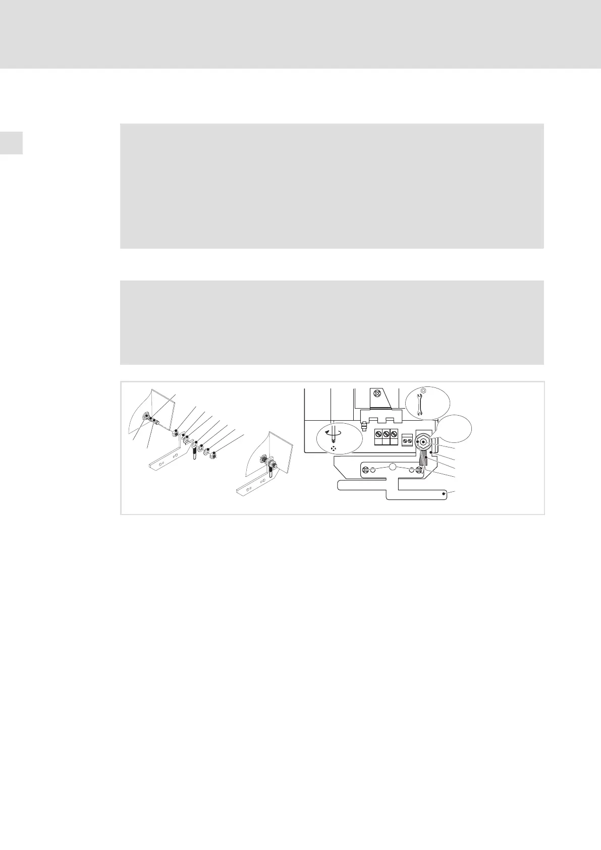
Fig. 5−4 Installation of shield sheet for drive controllers 0.37 ... 11 kW
PE stud
Screw on M5 nut and tighten hand−tight
Slide on fixing bracket for shield sheet
Slide on serrated lock washer
Slide on PE cable with ring cable lug
Slide on washer
Slide on spring washer
Screw on M5 nut and tighten it
Screw shield sheet on fixing bracket with two M4 screws (a)
 Loading...


