Electrical installation
Standard devices in the power range 0.37 ... 11 kW
Mains connection: Fuses and cable cross−sections
5
170
EDKVF9333V DE/EN/FR 7.2
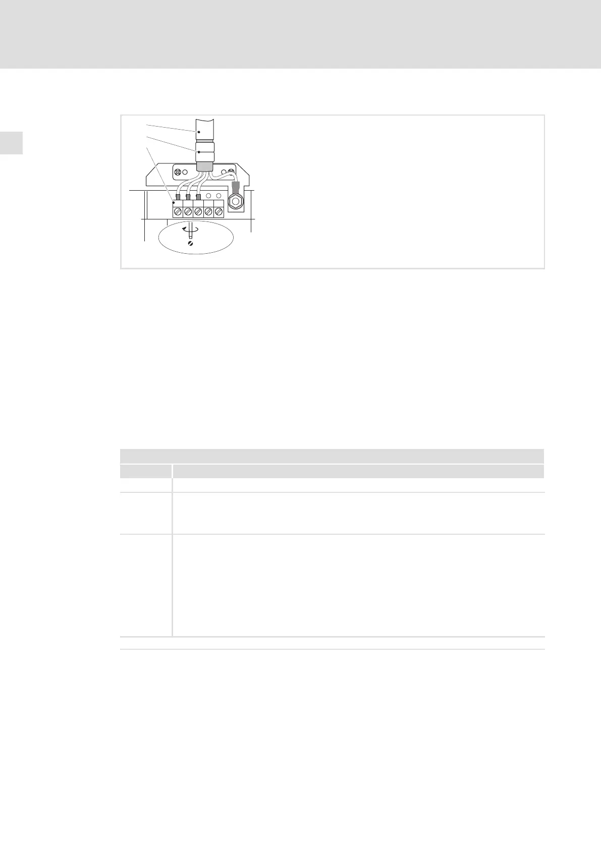
Mains connection, DC supply
L1 L2 L3
+UG -UG
PE
L1, L2, L3
+U , -U
GG
0.5...0.6 Nm
4.4...5.3 lb-in
2
0
1
9300std033
Fig. 5−3 Mains connection, DC supply for drive controllers 0.37 ... 11 kW
Mains cable
Shield sheet
Securely clamp mains cable with the lugs
Mains and DC bus connection
L1, L2, L3: Connection of mains cable
+U
G
, −U
G
: Connection of DC−bus components or connection of the controller in the DC−bus
system (see system manual)
Cable cross−sections up to 4 mm
2
: Use wire end ferrules for flexible cables
Cable cross−sections > 4 mm
2
: Use pin−end connectors
5.4.3 Mains connection: Fuses and cable cross−sections
Installation in accordance with EN 60204−1
Supply conditions
Range Description
Fuses l Utilisation category: only gG/gL or gRL
Cables Laying systems B2 and C: Use of PVC−insulated copper cables, conductor temperature < 70 °C,
ambient temperature < 40 °C, no bundling of the cables or cores, three loaded cores. The data are
recommendations. Other dimensionings/laying systems are possible (e.g. in accordance with
VDE 0298−4).
RCCB l Controllers can cause a DC current in the PE conductor. If a residual current device (RCD) or a
fault current monitoring unit (RCM) is used for protection in the case of direct or indirect
contact, only one RCD/RCM of the following type can be used on the current supply side:
– Type B (universal−current sensitive) for connection to a three−phase system
– Type A (pulse−current sensitive) or type B (universal−current sensitive) for connection to a
1−phase system
Alternatively another protective measure can be used, like for instance isolation from the
environment by means of double or reinforced insulation, or isolation from the supply system
by using a transformer.
l Earth−leakage circuit breakers must only be installed between mains supply and controller.
Observe all national and regional regulations!
 Loading...


