Electrical installation
Standard devices in the power range of 55 kW
Motor connection
5
192
EDKVF9333V DE/EN/FR 7.2
5.6.5 Motor connection
Note!
ƒ Fusing the motor cable is not required.
ƒ The drive controller features 2 connections for motor temperature
monitoring:
– Terminals T1, T2 for connecting a PTC thermistor or thermal contact
(NC contact).
– Pins X8/5 and X8/8 of the incremental encoder input (X8) for connecting a
KTY thermal sensor.
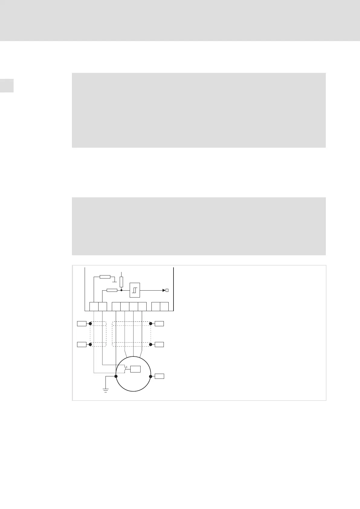
Motor with PTC thermistor or thermal contact (NC contact)
Wire T1, T2 only if the motor is equipped with a PTC thermistor or thermal contact
(NC contact).
ƒ An "open" cable acts like an antenna and can cause faults on the drive controller.
Danger!
ƒ All control terminals only have basic insulation (single isolating distance)
after connecting a PTC thermistor or a thermal contact.
ƒ Protection against accidental contact in case of a defective isolating
distance is only guaranteed through external measures, e. g. double
insulation.
PE
U
VW
T1 T2
+UG -UG
PES
PES
PE
M
3~
J>
PES
PES
PES
2.7 k
MONIT-OH8
15 V
3.3 k
7.4 k
9300vec139
Fig. 5−16 Circuit diagram of motor connection with PTC thermistor or thermal contact (NC contact) at T1, T2
 Loading...


