Mechanical installation
Standard devices in the power range 15 ... 30 kW
Thermally separated mounting (push−through technique)
4
150
EDKVF9333V DE/EN/FR 7.2
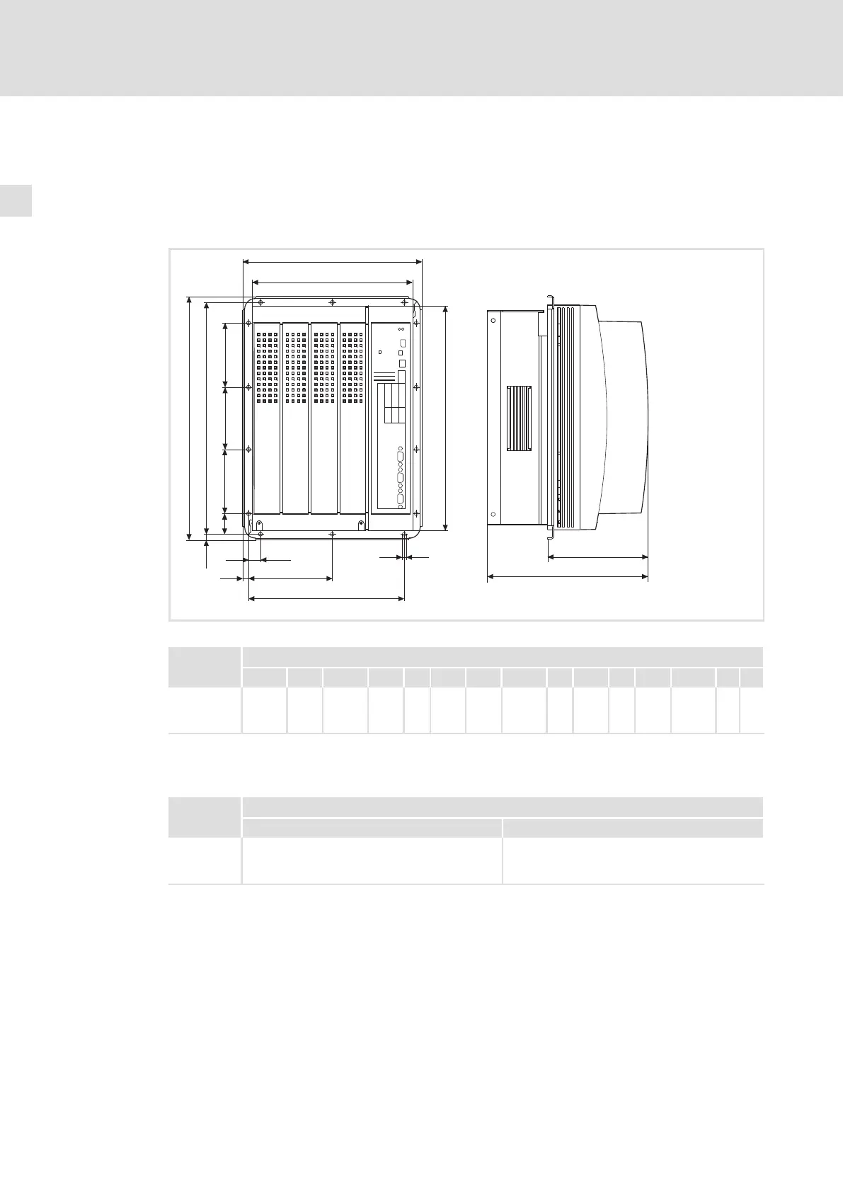
4.2.3 Thermally separated mounting (push−through technique)
For mounting in push−through technique, the drive controller of type EVF93xx−EV must be
used. In addition, the mounting set EJ0011 for push−through technique is required.
Dimensions
h
c1
c2
c3
h
d1
d2
d3
d2
d
b
a1
a
g
b1
e1
e
L
9300vec116
Fig. 4−5 Dimensions for thermally separated mounting 15 ... 30 kW
9300 vector Dimensions [mm]
Type a a1 b b1 c1 c2 c3 d d1 d2 d3 e
1)
e1 g h
EVF9327−EV
EVF9328−EV
EVF9329−EV
279.5 250 379.5 350 19 131 243 361.5 32 100 97 250 159.5 6 9
1)
For a fieldbus module plugged onto X1, consider mounting space for connecting cables
Mounting cutout in control cabinet
9300 vector Dimensions [mm]
Type Width Height
EVF9327−EV
EVF9328−EV
EVF9329−EV
236 336

 Loading...


