Electrical installation
Standard devices in the power range 0.37 ... 11 kW
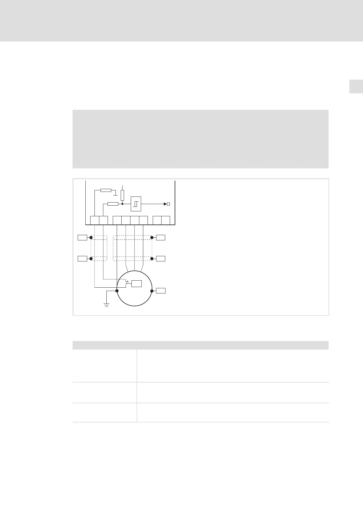
Motor connection
5
175
EDKVF9333V DE/EN/FR 7.2
Motor with PTC thermistor or thermal contact (NC contact)
Wire T1, T2 only if the motor is equipped with a PTC thermistor or thermal contact
(NC contact).
ƒ An "open" cable acts like an antenna and can cause faults on the drive controller.
Danger!
ƒ All control terminals only have basic insulation (single isolating distance)
after connecting a PTC thermistor or a thermal contact.
ƒ Protection against accidental contact in case of a defective isolating
distance is only guaranteed through external measures, e. g. double
insulation.
PE
U
VW
T1 T2
+UG -UG
PES
PES
PE
M
3~
J>
PES
PES
PES
2.7 k
MONIT-OH8
15 V
3.3 k
7.4 k
9300vec139
Fig. 5−5 Circuit diagram of motor connection with PTC thermistor or thermal contact (NC contact) at T1, T2
Characteristics of the connection for motor temperature monitoring:
Terminals T1, T2
Connection l PTC thermistor
– PTC thermistor with defined tripping temperature (acc. to DIN 44081 and
DIN 44082)
l Thermal contact (NC contact)
– Thermostat as NC contact
Tripping point l Fixed (depending on the PTC/thermal contact)
l PTC: RJ
> 1600 W
l Configurable as warning or error (TRIP)
Notes l Monitoring is not active in the Lenze setting.
l If you do not use a Lenze motor, we recommend the use of a PTC thermistor up
to 150°C.
 Loading...


